Zen Mod said:in both cases difference is slightly above 10% rise of mains voltage.....
for me that looks as nothing to care , if heatsinks are good enough
regarding power-that really depends on load (spks he use),nothing more ....and nothing less")
grimberg said:Shawn,
You can use a CLC filter in your PSU and the choke will help drop the voltage a bit. Hammond has a 2.5mH, 10A model, the code is 159ZL, that I used in my Aleph 2.
I don' t feel that far out on a limb here. I'm a cautious person.How common is the CLC on solid state designs? Sounds kinda audiophile-ish to me.
I have four very large chokes that I pulled when I picked up my 1kVA toroids. I measured them last year and I currently can't recall the value, it doesn't matter as Hammond is a 45 minute drive away. I have been there a few times already picking up parts. I'm cool,
Shawn.
TomWaits said:I don' t feel that far out on a limb here.
I agree, am just trying to help...
Sounds kinda audiophile-ish to me.
I don't consider myself an audiophile (thank God!), but I frequently use CLC PSUs in my projects.
Hammond is a 45 minute drive away
That's what I figured, and the reason why I suggested their product.
And if you decide on using an r-theta extrusion, I would gladly split the cost with you.
Originally posted by grimberg
I agree, am just trying to help...
That was a general statment. I didn't mean it in a harsh way.
I don't consider myself an audiophile (thank God!), but I frequently use CLC PSUs in my projects.
I say that 'cause they are more often found, if not required, in valve designs. I see them as lazy and inefficient but here I am talking about class A!
I just never thought of using them on a solid state piece. It is a "get of of jail card" too for high supplies.
And if you decide on using an r-theta extrusion, I would gladly split the cost with you.
It sounds like you are building or want to build a KSA50? Well I'm kind of getting geared up to use this little tunnel I have which would put me out of the picture. And then I now have 8 pieces of another extrusion that look very Krellish/Mark & Levinsionish that I could use too. I guess R-theta is not in my near future, plus it takes volume to crack their prices into something more reasonable but please let me know if I can be of further assistance.
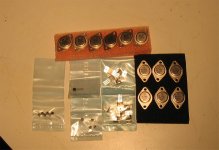
On another topic, Digi-Key has outstanding service! They even phoned me on my cell phone yesterday to change my order a little to save me money and time getting shipments into Canada! The little box was here this morning. Outstanding service for a catalog house. They sent they attached.
Cheers,
Shawn.
Attachments
just try it ,then talk.TomWaits said:
I don' t feel that far out on a limb here. I'm a cautious person.How common is the CLC on solid state designs? Sounds kinda audiophile-ish to me.
I'm cool,
Shawn.
or-fiddle little with PSUd ,so you can see........
sometimes little tooobie thinking is good

Zen Mod said:
just try it ,then talk.
or-fiddle little with PSUd ,so you can see........
sometimes little tooobie thinking is good
Great quote! Andy T already suggested I have a look see with PSUd for calculating and predicting supplies, I have not yet done this.
I should and I will.Thanks,
Shawn.
TomWaits said:
Great quote! Andy T already suggested I have a look see with PSUd for calculating and predicting supplies, I have not yet done this.
Thanks,
Shawn.
hehe-I'm smart ,as usuall.........
just look at this example (attached) - 3mV ripple at output,4A Iq (both channels of Babelfish)
btw-that's zipped PSUd file
Attachments
Zen Mod said:hehe-I'm smart ,as usuall.........
just look at this example (attached) - 3mV ripple at output,4A Iq (both channels of Babelfish)
btw-that's zipped PSUd file
You're forcing me to do the right thing! How clever...PSUd downloading....
Shawn.
TomWaits said:
You're forcing me to do the right thing! How clever...PSUd downloading....
Shawn.
I'm here-waiting for your "Whoa! Blue car!!" ....when you see difference between filter with and without choke........

choke placed in right place can save you crazy amount of capacitance,and you can still have benefits of pretty fast supply......and that you can't have with zillion Farads.........
capacitance is not everything, PSU recovery is often broomed in deepest corner.....and-when you have choke where you want.......that filter can run in circles around slower and heftier one........
TomWaits said:How common is the CLC on solid state designs?
To quote Bob Candy Cordell: Not on consumer garbage.
But some of the big names have used choke powersupplies as far back as 20 years ago, even class AB amplifiers.(the transformer variety)
Not really common either in the major league, not even Nelson Pass used it in his first Aleph amps in the early 90s.
Advantage nowadays is ease of getting thick wire diameter air coils.
Before the Aleph era started you'd tediously have to wind your own, after months of locating a supplier of thick enamelled wire of sufficient length.
Before that, trying your luck with EI-cores, the so called Zero Ohm coils, and pray they don't saturate.(expensive stuff)
I used to pull choke transformer coils out of gear like brokendown running band exercise machines.
(can post a pic of one of those coils if liked)
Once you've diy-ed an SE with a CLC, it becomes addictive.
Some shops in the US sell air coils at very good rates (judging from my end of the stick anyways)
Setting up a CLC with Duncan Munro's PSUd is like getting candy, calculating by hand is tedious labour.
Jacco/Andrew/Stuart and others:
(Pinky feel free to delete this post as it does not relate to the KSA50 but then where will I find such talent in one thread. )
I have a couple of Nelson's old Forte 3's. (200wpc -AB) they are running a 2 ohm load is taxing them (Sonically). Using just one channel of each amp... other not loaded.
I cannot help but think this is not efficient use of 2 power amps.
I have 2 options: Parallel bridge 2 channels to make one hefty channel. (By decoupling one channel's input VA stages and running both OP stages by the other channel's input/VA stage.)
Option 2: Run the Trafo primary in series, reducing the rails by 50% and running both channels serial bridged.
Questions:
1) Under which arrangement will I be able to get more class-A biasing (I am guessing parallel)
2) Will the serial bridged OP be able to run a 2 ohm load?
3) What kind of class-A levels can I expect from the serial bridge arrangement.
The current OP stage is 4 pairs of the 3281/1302's running off 75 vdc rails. After serially bridging them there will be 8 pairs running off 37.5 vdc rails.
I am leaning towards bridging because i have always liked the less grainy sound of many bridged amps (as long as the loads were not hairy and the rails were not high).
Once again apologies for sticking this question in this thread. you guys can reply on my personal email.
Best,
K-fed-up
(Pinky feel free to delete this post as it does not relate to the KSA50 but then where will I find such talent in one thread.
)I have a couple of Nelson's old Forte 3's. (200wpc -AB) they are running a 2 ohm load is taxing them (Sonically). Using just one channel of each amp... other not loaded.
I cannot help but think this is not efficient use of 2 power amps.
I have 2 options: Parallel bridge 2 channels to make one hefty channel. (By decoupling one channel's input VA stages and running both OP stages by the other channel's input/VA stage.)
Option 2: Run the Trafo primary in series, reducing the rails by 50% and running both channels serial bridged.
Questions:
1) Under which arrangement will I be able to get more class-A biasing (I am guessing parallel)
2) Will the serial bridged OP be able to run a 2 ohm load?
3) What kind of class-A levels can I expect from the serial bridge arrangement.
The current OP stage is 4 pairs of the 3281/1302's running off 75 vdc rails. After serially bridging them there will be 8 pairs running off 37.5 vdc rails.
I am leaning towards bridging because i have always liked the less grainy sound of many bridged amps (as long as the loads were not hairy and the rails were not high).
Once again apologies for sticking this question in this thread. you guys can reply on my personal email.
Best,
K-fed-up
K-amps said:talent in one thread
Try your shoe lace.
K,
How do you spot a con-artist ?
Easy, wooden shoes don't have laces !
Seriously,
if your Forte Audio M3 didn't hit that thermal braker on the heatsink and those nice Toshies didn't turn Central-Africa then the PS saved them because it's anaemic at 2 ohms use.
Which is not a miracle, i had one of the earlier Class A Forte models.
Worked great in low imp loads, but had about the same layout with way lower rail voltages.
(i used to have dreams about glueing a piece of paper on the front with SA-Slash printed on it)
Those big wattage Forte amps were supposed to run normal loudspeakers, not the crematory.
Whether you half the rail voltages and bridge it, or place the output stages in parallel, makes no difference.
Whether half rail voltage/number of parallel devices or full voltages/number can make a difference for the Tosh SOA.
But you'd still have the 2 Ohm load, and 75V across it.
=> same peak current=> same load the PS can't deliver.
For 75V rails in 2 Ohms the ForteA toroid would have to be at least 50% heftier.
Class A bias level makes little difference, whether parallelled or bridged.
Expect a lower clean power figure when bridged, see my response to Stuarts post on bridging.
You can place a bull behind a cow, but if he did not have his cereals there be no flaggin the queen.
If you need more current:
- bigger toroid
- lower the effective voltage across the load
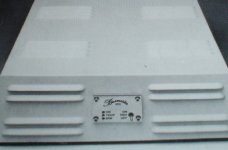
The pic down below is a bridged 100/8 monaural amp that had those Toshiba numbers.
It could be set to 2/1 ohms use through a lower PS voltage, 100Wattsthat in 2 and 160W in 1 Ohm.
1/2 the rail voltage and 2 times the output current=> same VA rating for the transformer.
That musician/designer guy from the Old Reich again
How do you spot a con-artist ?
Easy, wooden shoes don't have laces !
Seriously,
if your Forte Audio M3 didn't hit that thermal braker on the heatsink and those nice Toshies didn't turn Central-Africa then the PS saved them because it's anaemic at 2 ohms use.
Which is not a miracle, i had one of the earlier Class A Forte models.
Worked great in low imp loads, but had about the same layout with way lower rail voltages.
(i used to have dreams about glueing a piece of paper on the front with SA-Slash printed on it)
Those big wattage Forte amps were supposed to run normal loudspeakers, not the crematory.
Whether you half the rail voltages and bridge it, or place the output stages in parallel, makes no difference.
Whether half rail voltage/number of parallel devices or full voltages/number can make a difference for the Tosh SOA.
But you'd still have the 2 Ohm load, and 75V across it.
=> same peak current=> same load the PS can't deliver.
For 75V rails in 2 Ohms the ForteA toroid would have to be at least 50% heftier.
Class A bias level makes little difference, whether parallelled or bridged.
Expect a lower clean power figure when bridged, see my response to Stuarts post on bridging.
You can place a bull behind a cow, but if he did not have his cereals there be no flaggin the queen.
If you need more current:
- bigger toroid
- lower the effective voltage across the load
The pic down below is a bridged 100/8 monaural amp that had those Toshiba numbers.
It could be set to 2/1 ohms use through a lower PS voltage, 100Wattsthat in 2 and 160W in 1 Ohm.
1/2 the rail voltage and 2 times the output current=> same VA rating for the transformer.
That musician/designer guy from the Old Reich again
Attachments
Re: Re: Re: Input Stage devices
Shawn, here (from my LM4780 Page) is a fan control circuit.
R2 and R3 with S1 change the fan speed. I have S1 and R3 on the rear panel. So typically S1 is connected such that R2 is open circuit and R3 by itself sets the speed, which is the typical speed that keeps things cool. If I want to slow the speed down I flip S1 and bring in R3 which adds resistance and drops the output voltage, I can then turn R3 to set the speed to any slower amount I want. To go back to my "factory" setting I just open circuit R3 by flipping the switch again.
I've been using this for a few months and it works great.
Edit- a simpler way to do this would be to omit S1 and R3 and just control the speed via variable R2, but watch out if your supply is over 12VDC (or the max fan voltage) because you will then have the option of blowing up your fan.
TomWaits said:
I'll check out the Pabstman!
***
Now how about that variable fan control circuit?
Cheers,
Shawn.
Shawn, here (from my LM4780 Page) is a fan control circuit.
R2 and R3 with S1 change the fan speed. I have S1 and R3 on the rear panel. So typically S1 is connected such that R2 is open circuit and R3 by itself sets the speed, which is the typical speed that keeps things cool. If I want to slow the speed down I flip S1 and bring in R3 which adds resistance and drops the output voltage, I can then turn R3 to set the speed to any slower amount I want. To go back to my "factory" setting I just open circuit R3 by flipping the switch again.
I've been using this for a few months and it works great.
Edit- a simpler way to do this would be to omit S1 and R3 and just control the speed via variable R2, but watch out if your supply is over 12VDC (or the max fan voltage) because you will then have the option of blowing up your fan.
Hallo alles!
Another Krell is on the verge of playing sweet music!
As of now the amp is connected to a small portable MP3-player running on half volume and connected to some cheap 8ohm speakers.
However, there are some strange stuff going on here. The bias is set to approx 45mV measured over Re1 but nowhere close to the 1,2V across R127 stated in the WIKI, more like 600mV and even if the DC-offset can be lowered this action seems to lower the bias quite a lot.
The amp is running two channels on one big 2x30VAC 1KVA transformer and one pair of mje15003 and 15004 on each channel.
Edit, managed to read 40mV instead of 400mV....
kmj said:And we can only raise the bias one one channel. We started to raise the right channel to the stated 45mV and without touching the DC-ofset went over to the right channel. When turning the pot nothing happens to the bias, it stays at approx 11,4mV
any idéas?
MArk G. have problems with testing new Krell proto in The Other Thread;
you can try few things mentioned there.
double check resistor values and positioning around VAS and drivers
We have now raised the bias to 200mV across Re1 on both channels and offset is below 10mV and everything seems alright as far.
Only one thing...
The WIKI says 400mV across the emitterresistors. This means 400mV across EACH of the resistors, not across a PAIR of resistors, right?
So when we measure 200mV by placing one probe on each pin on one resistor there should be 400mV as I understand it, correct?
Only one thing...
The WIKI says 400mV across the emitterresistors. This means 400mV across EACH of the resistors, not across a PAIR of resistors, right?
So when we measure 200mV by placing one probe on each pin on one resistor there should be 400mV as I understand it, correct?
Hi Kmj,
what value of emitter resistor have you used?
Use ohm's law to find the current in each emitter resistor.
I=V/R
Add up the currents for each of the three emitter resistors in the positive half and do the same for the negative half. The two sums should be the same, because there is no load fitted.
That is your Iq.
Because you have a push pull circuit the peak ClassA current is 2*Iq.
The ClassA power into 8ohms is [2*iq]^2 * 8
The result of all this is that half Vre gives quarter ClassA power (about 12W).
Sounds like you have a resistor error.
Power down, let the PSU voltage go down to 0.1V and hold it there for a few minutes.
Try measuring the value of the bias pot when Iq is at maximum. It should be near zero (<1r0)
- Home
- Amplifiers
- Solid State
- Krell KSA 50 PCB