case Post #3468
Worked on my case for 6 hrs yesterday; attaching wood side panels, drilling more holes for ventilation, installing a second fan. I've got a 50 mm fan blowing air in from the bottom and a 120mm fan at the top blowing air out. Man, the mechanical aspects of diy are extremely time consuming.
Hey Terry- hows the case coming?
you can't just dangle something like that infront of people and then leave it at that.....
Pictures good Sirs, pictures

kmj said:
you can't just dangle something like that infront of people and then leave it at that.....
Pictures good Sirs, pictures
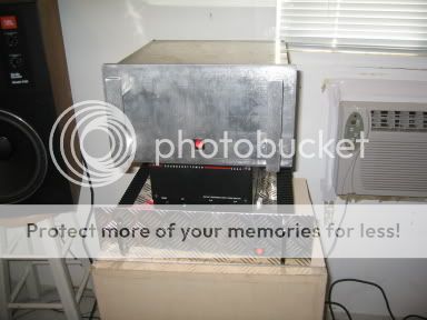
OK folks, I finished making a case. I need to do some more touch-up on it, but it is together and playing. Here are some pics.
Front veiw after assembly. That is a Soundcraftmen S860 bellow it and my P101 below that. I am still doing listening tests between them.
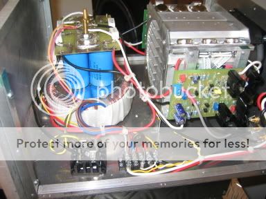
Right side with side covers removed. You can see the thermistor mounted on the patch panel.
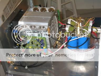
Left side.
Rear view. Notice I extended the sides to protect the plugs in back.
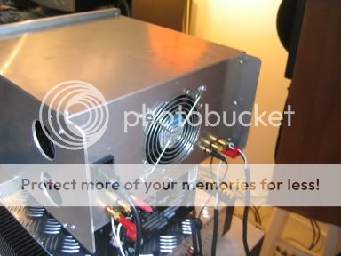
Heres a view of the intake holes in the sides. As you can see they are directly in front of the drivers. With the sides off the drivers were running at 75c. With sides and top instakked the drivers are running at 45c. I still need to install some type of screen over the intakes.
Here's a pic of the JBLs I'm listening to it through.
It sounds best hooked up through all four speakers and running at 4 ohms.

I've got to say this amp sounds very, very nice. It is really making that little window shaker work though.
I wanted to tell of something I learned when putting this in the case. Fist of all I tried using a long brass bolt as the hold-down for the toroid as well as the star ground. I got a horrible hum. In the pics you can now see two bolts sticking up through the top of the filter caps. One still goes all the way down to the bottom of the case and serves as the mount for both the toriod and the filter caps but it is isolated from the ground plain on the caps. The other bolt only conects to the ground plane and serves as the star. No hum at all now.
Blessings, Terry
Nice to get some pictures
And i must say that i REALLY like that tunnelsink.
btw, a while back you boys discussed different softstarts and something that originated from an earlier Pass Labs amplifier as i understood it (CL-60, right?) which is a thermstor.
Is this as good as a genuine softstart, for axample, the earlier "Spaceshuttle" or the one peranders has?
btw, a while back you boys discussed different softstarts and something that originated from an earlier Pass Labs amplifier as i understood it (CL-60, right?) which is a thermstor.
Yea, The softstarts that people design are certainly nice but pretty rediclous overall and usually much more complicatd than the amps they are put into. The CL-60 and its cousins do EXACTLY the same thing for just a couple of bucks. All my Pass Labs and Krells so far have the CL-60's in them and the problem rate is zero. For those that can't tolerate a volt and a half or so of drop across the thermistor its super easy to short the thing out after a two second delay with a simple 555 timer circuit, this only adds a few bucks to the price of the CL-60.
Mark
KMJ,
But the ones from Mouser will NOT become moldy and spoil.
___________________________________________________
Attention Group Board Buyers!!!!
The board seems to be working just fine so the order will go in tomrrow for them. I will post the expected delivery date of the boards to me later this week so you can all get an idea of when you might expect to receive them. Starting the day after I receive them I will be mailing them out over about a weeks time. They will ship out in the order that the payments were received so that means that Al's will be the first boards out of here and Jacco the second, and Stuart the third and so on and so forth. I think this is the fair way to handle shipment to so many places.
_______________________________________________
Nice case Terry!! How much would you charge to build one for me? Thats exactly what I need.
Mark
hold your breath...
Also spent some time bringing 4 emitter resistor leads out to the case with a connector for easier bias adjustment without full disassembly. Don't know if this is a good idea or not but seemed like the thing to do. Lost my AC inlet, it broke while I was working on the case. Two steps foward one back, still progress.
Terry, that looks great, mine is not as neat and my drilling skills and metal skills are way below yours.
I'm on a business trip all week in Canada, but when I get back to sunny San Diego you will have a pic or 2.
kmj said:
you can't just dangle something like that infront of people and then leave it at that.....
Pictures good Sirs, pictures
Also spent some time bringing 4 emitter resistor leads out to the case with a connector for easier bias adjustment without full disassembly. Don't know if this is a good idea or not but seemed like the thing to do. Lost my AC inlet, it broke while I was working on the case. Two steps foward one back, still progress.
Terry, that looks great, mine is not as neat and my drilling skills and metal skills are way below yours.
I'm on a business trip all week in Canada, but when I get back to sunny San Diego you will have a pic or 2.
Hi, I'm hoping someone can help me with the following:
If I were to increase the bias of the amplifier in order to obtain 150Wrms into 4ohms, should any component values, except for the transformers, number of output transistors and heatsink thermal resistance, change? Would 1/2W resistors still suffice in this case?
Thank you in advance.
Paul
If I were to increase the bias of the amplifier in order to obtain 150Wrms into 4ohms, should any component values, except for the transformers, number of output transistors and heatsink thermal resistance, change? Would 1/2W resistors still suffice in this case?
Thank you in advance.
Paul
Terry
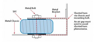
If you look at the attached picture you can see why you got that terrible hum in the first place. I used the picture from BrianGT's manual because that explains very well how to bolt down a toroid transformer in a casing. Always make sure that you never ever create a shorted turn with the centerbolt.
Regards
Fist of all I tried using a long brass bolt as the hold-down for the toroid as well as the star ground. I got a horrible hum. In the pics you can now see two bolts sticking up through the top of the filter caps. One still goes all the way down to the bottom of the case and serves as the mount for both the toriod and the filter caps but it is isolated from the ground plain on the caps. The other bolt only conects to the ground plane and serves as the star. No hum at all now.
If you look at the attached picture you can see why you got that terrible hum in the first place. I used the picture from BrianGT's manual because that explains very well how to bolt down a toroid transformer in a casing. Always make sure that you never ever create a shorted turn with the centerbolt.
Regards
Attachments
JoeyDD said:If I were to increase the bias of the amplifier in order to obtain 150Wrms into 4ohms, should any component values change?
For 150 watts continuous class A power in 4 you should count on +350 watts of dissipation.
With a few rare exceptions, PS voltage of an amplifier will drop at such bias current.
To really be able to get 150 watts in class A in 4 ohms you will need to raise rail voltage with 2 volts or more, think 40 vdc rails.
My general rule is equal temperature rise for heatsink and output devices. Unless you are thinking of extraordinary cooling you will need 12 output devices for such high dissipation.
150 watts in 4 ohm means 8.7 amps peak output current.
Per device that is 0.13 amp biasing current more than for 50 watts class A in 8 ohms with 6 output devices.
That is less than 0.1v higher voltagedrop over a 0.68 ohm emitter resistor, means you have to put about 0.1 volts more on the drivers with the trimmpot.
As a result your driver current will increase by about 30 mA.
Compared to 50 watts class A and 6 devices the dissipation of the driver will be ~ 3.5 watts instead of ~2.2 watts, a bigger sink for the driver may be a good choice.
The rest remains the same, no higher wattage resistors.
jacco vermeulen said:
For 150 watts continuous class A power in 4 you should count on +350 watts of dissipation.
With a few rare exceptions, PS voltage of an amplifier will drop at such bias current.
To really be able to get 150 watts in class A in 4 ohms you will need to raise rail voltage with 2 volts or more, think 40 vdc rails.
My general rule is equal temperature rise for heatsink and output devices. Unless you are thinking of extraordinary cooling you will need 12 output devices for such high dissipation.
150 watts in 4 ohm means 8.7 amps peak output current.
Per device that is 0.13 amp biasing current more than for 50 watts class A in 8 ohms with 6 output devices.
That is less than 0.1v higher voltagedrop over a 0.68 ohm emitter resistor, means you have to put about 0.1 volts more on the drivers with the trimmpot.
As a result your driver current will increase by about 30 mA.
Compared to 50 watts class A and 6 devices the dissipation of the driver will be ~ 3.5 watts instead of ~2.2 watts, a bigger sink for the driver may be a good choice.
The rest remains the same, no higher wattage resistors.
I run ~136w FULL Class A into 4 ohm...... I think they are 36-37vdc rails..... it puts out huge amount of heat.... draws 770w from the mains at idle (!)... Maybe i'm getting more than 136w class A
I use 5 output PAIRS per channel and big heatsinks with 3 fans on each..
Aaron
Oops, I forgot to insert the pic of the drivers next to the intake holes, so I'll do it now.
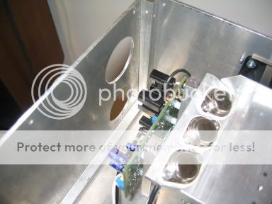
I was really amazed at how big of a temperature drop I got on the drivers by doing this. As I was testing this all week before I built the case, the drivers were running between 70c and 75c. I figured this was too high so I took that into consideration when planning the intake for the case. Worked like a dream. Like I said earlier, the temp dropped to 45c due to the air flow being forced over them.
I was wondering what happened to that extra voltage. All week while testing this amp out of the case, I was reading about 42VDC rails. After installing it into the case and adding the CL-60 thermistor, I am anly reading a little over 40V rails. This explains it. Thanks.
Sorry Mark, that case took me two days to make and about $60 worth of materials and I'm still not satisfied with the way it looks. I would hate to try and make one for someone else. I need to sleep at night.
I had seen that diagram before with the toroid. I guess I hadn't realized that the wires were creating the loop that is indicated in the diagram with metal plate. It was a lesson learned and I only mentioned it to save someone else from going through it too. THis amp is very quiet now. I still may add the 100uf resistors across the bridge and incoming current, that had been suggested in an earlier post. I bought them and then forgot to install them. I may do that tonight when I get home.
Blessings, Terry
I was really amazed at how big of a temperature drop I got on the drivers by doing this. As I was testing this all week before I built the case, the drivers were running between 70c and 75c. I figured this was too high so I took that into consideration when planning the intake for the case. Worked like a dream. Like I said earlier, the temp dropped to 45c due to the air flow being forced over them.
All my Pass Labs and Krells so far have the CL-60's in them and the problem rate is zero. For those that can't tolerate a volt and a half or so of drop across the thermistor its super easy to short the thing out after a two second delay with a simple 555 timer circuit, this only adds a few bucks to the price of the CL-60.
I was wondering what happened to that extra voltage. All week while testing this amp out of the case, I was reading about 42VDC rails. After installing it into the case and adding the CL-60 thermistor, I am anly reading a little over 40V rails. This explains it. Thanks.
Nice case Terry!! How much would you charge to build one for me? Thats exactly what I need.
Sorry Mark, that case took me two days to make and about $60 worth of materials and I'm still not satisfied with the way it looks. I would hate to try and make one for someone else. I need to sleep at night.
If you look at the attached picture you can see why you got that terrible hum in the first place. I used the picture from BrianGT's manual because that explains very well how to bolt down a toroid transformer in a casing. Always make sure that you never ever create a shorted turn with the centerbolt.
I had seen that diagram before with the toroid. I guess I hadn't realized that the wires were creating the loop that is indicated in the diagram with metal plate. It was a lesson learned and I only mentioned it to save someone else from going through it too. THis amp is very quiet now. I still may add the 100uf resistors across the bridge and incoming current, that had been suggested in an earlier post. I bought them and then forgot to install them. I may do that tonight when I get home.
Blessings, Terry
NUTTTR said:
I run ~136w FULL Class A into 4 ohm...... I think they are 36-37vdc rails..... it puts out huge amount of heat.... draws 770w from the mains at idle (!)... Maybe i'm getting more than 136w class A
I use 5 output PAIRS per channel and big heatsinks with 3 fans on each..
Aaron
Hi Aaron,
I have been wondering something and your post reminded me to ask. How do you know that you are actually getting 136w output? How does one go about measuring that? I would love to know how much output I am getting from the amps I've built. Is there a way of measuring this with a multimeter or does it take special equipment?
Thanks, Terry
Upupa Epops said:While somewhere in the world poor people cook on dropings of camel, rich guys wastage energy in amps with superlow efficiency only for good feeling. Oh, what crazy world !
Do I take by this that you are not a fan of Class A poweramps?
Blessings, Terry
still4given said:I was really amazed at how big of a temperature drop I got on the drivers by doing this.
Very ingenious, Terry.
While somewhere in the world poor people cook on dropings of camel
I dont mind cooking my Camels on an amplifier, i hate dropping my fags though.
still4given said:
Hi Aaron,
I have been wondering something and your post reminded me to ask. How do you know that you are actually getting 136w output? How does one go about measuring that? I would love to know how much output I am getting from the amps I've built. Is there a way of measuring this with a multimeter or does it take special equipment?
Thanks, Terry
Terry you can calculate it based on the voltage drop across the emitter transistors. (For class-A level). As for total power, I use the crude old way of injecting a 1kHz sinewave into a 4 ohm dummy load and watch the wave run into clipping on a scope. Once you see the clipped crest, back it off a notch till you see the wave rounded and read the RMS Ac voltage (you need a true RMS meter for it). AC voltage squared divided by 4 ohms is your power level, You can repeat the procedure for 20Hz and 20,000Hz and take the lower of the two as your output.
K-
K-amps said:
Terry you can calculate it based on the voltage drop across the emitter transistors. (For class-A level). As for total power, I use the crude old way of injecting a 1kHz sinewave into a 4 ohm dummy load and watch the wave run into clipping on a scope. Once you see the clipped crest, back it off a notch till you see the wave rounded and read the RMS Ac voltage (you need a true RMS meter for it). AC voltage squared divided by 4 ohms is your power level, You can repeat the procedure for 20Hz and 20,000Hz and take the lower of the two as your output.
K-
Yup that's it! For Class A power output i used the spreadsheet calculator, i actually have a meter for measuring the kW drain on the mains
So i know exactly what is going in... For testing power output you really need a scope!
You can take a "guess" by using rail voltage, etc.... Or you can use the spreadsheet for approx values..
Aaron
- Home
- Amplifiers
- Solid State
- Krell KSA 50 PCB