jacco vermeulen said:Arif,
even with 100v rails resistors like r103 and r107, with a voltagedrop of 99.4v, still need less than 0.25 watt.
Even with 1 watters, others will die without Stuart's extra's, like R108/109.
So why the need for 1 watt resistors ?

ok ok .... Quarter watters are ok with me.
Re: power...
Stuart,
Will the 970/2240 need to be replaced even with the CCS?
Stuart Easson said:
Once the rails are beyond 60v the 2sa970 and 2sc2240 don't have enough Vce to be completely safe, and I substituted the mpsa types for my tests.
Stuart
Stuart,
Will the 970/2240 need to be replaced even with the CCS?
I used MDL 4's with the CL-60's in place and they hold fine after several months. I am at +/-38 volt rails and 400 ma idle across the emitter resistors.
I don't advocate using rail fuses because none of us really quite know how much DC might appear at the output terminals if one should simply overload the amp and pop a rail fuse.... you may not dmage the amp, but you may destroy your speaker on that channel!! I don't believe that the original KSA 50 had rail fuses in it.......
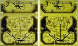
THE PROTOS ARE IN! The improvements do appear to allow mounting the boards in a much safer manner. The foil has been moved away from the mounting holes and the mounting holes have been moved outwards as well, so thats much, much better. The wire holes that have been changed to larger holes will now accomodate #12 stranded silver plated teflon wire with ease . All in all with the few changes made the new version should accomodate everyones wire type usage. I will post side by side photos of the first version and the revised version later on tonight so check back here.
Thanks Al for all your work on this board! I don't think we could expect it to be any better than it is now.
Mark
I don't advocate using rail fuses because none of us really quite know how much DC might appear at the output terminals if one should simply overload the amp and pop a rail fuse.... you may not dmage the amp, but you may destroy your speaker on that channel!! I don't believe that the original KSA 50 had rail fuses in it.......
THE PROTOS ARE IN! The improvements do appear to allow mounting the boards in a much safer manner. The foil has been moved away from the mounting holes and the mounting holes have been moved outwards as well, so thats much, much better. The wire holes that have been changed to larger holes will now accomodate #12 stranded silver plated teflon wire with ease
. All in all with the few changes made the new version should accomodate everyones wire type usage. I will post side by side photos of the first version and the revised version later on tonight so check back here.Thanks Al for all your work on this board! I don't think we could expect it to be any better than it is now.
Mark
I will post side by side photos of the first version and the revised version later on tonight so check back here.
Waiting with baited breath!
Blessings, Terry
Terry,
Its ok to breath now!!
I would like some feedback from everyone on how they look....... Want to be sure everyone is happy with them. I will builf one up tommrrow and is all is well the order will be placed on Monday. The 2 for 4 deal is still good till Aug, 4th so we will have the entire run back in 2 weeks from that time. The PSU boarsd willa lso go in via Brian GT on Monday and will have a similar production turn around time. The amp boards will be 2 oz copper and the PSU boards I am pretty sure are3 oz copper.
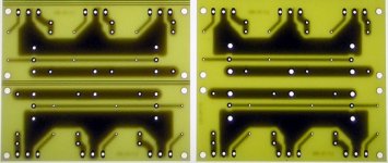
The first OUTPUT BOARD prototype is on the left, the final is on the right.....
Its ok to breath now!!
I would like some feedback from everyone on how they look....... Want to be sure everyone is happy with them. I will builf one up tommrrow and is all is well the order will be placed on Monday. The 2 for 4 deal is still good till Aug, 4th so we will have the entire run back in 2 weeks from that time. The PSU boarsd willa lso go in via Brian GT on Monday and will have a similar production turn around time. The amp boards will be 2 oz copper and the PSU boards I am pretty sure are3 oz copper.
The first OUTPUT BOARD prototype is on the left, the final is on the right.....
Attachments
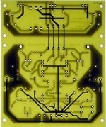
What makes this board so nice is that you can leave the main/driver board together(assuming enough heatsink for the drvices) and just jumper the traces over as shown. Or if you want you can snap them apart and easily mount the drivers to the main heat sink. They do run pretty hot.
Mark
Mark
Attachments
Cool!
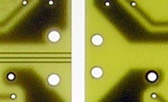
Mark, I take your point about the BOM, but it does show how robust the design is for a little variance in values. The boards look very nice, though I don't see the markings for the scoring.
Noob, these are proto boards, with no solder resist, scoring or silkscreen. The production boards will have all three. Unfortunately not in pink...
I completed my Softstart & Standby PCB. It is single side. It also includes an Main DC Filter. This is a low res file. I can send hires pdf if interested. I'll use it into my KSA50. In fact I was waiting for it before finishing the amp.
Attachments
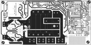
I completed my Softstart & Standby PCB. It is single side.
Nice design but I don't think there are that much electronics in the entire Space Shuttle! I'll stick with the CL-60 myself.
Al,
Yea, they left the scoring marks off for some reason and thats the only question I have for them on Monday when I place the order. Can you double check the file at your end to make sure they are still there.......
Thanks!
Mark
Mark A. Gulbrandsen said:Yea, they left the scoring marks off for some reason and thats the only question I have for them on Monday when I place the order. Can you double check the file at your end to make sure they are still there...
Yes, they were in the archive, the file is Gerber format, and called KSA50II.mil. I've attached it here as well, just in case
Oh, and could you resend that other file, we had a server crash at work as they were upgrading to XP, and it's difficult enough trying to get work related files from backups, so I don't really want to push them on that one as well!
Attachments
Hi guys
I just joined in on a group buy arranged by Maxhawk for a Soft Start kit . I was looking for such a device to use in my Krell clone and this seems to be the perfect thing. So for those who are also interested, click the link below.
http://www.diyaudio.com/forums/showthread.php?goto=newpost&threadid=61653
Regards
- Home
- Amplifiers
- Solid State
- Krell KSA 50 PCB