But first put the boards away, and leave them for two or three days, then come back with a fresh mind. I find that quite often then the problem is found within minutes.
That tactic has also worked for me in the past.
Regards
Mark A. Gulbrandsen said:I have not decided if I will charge a 3% Pay-Pay surcharge but I am leaning towards doing that so I don't get short changed myself.
Including the 3%, please.
You're doing a lot of the labor, along with Al, all of us should be gratefull to have decent sets of boards at such low cost.
Terry,
it doesnt matter that much if resistor values differ slightly, as long as you are sure you are using the same on both sides of the symmetric line. A 5K resistor with 1% accuracy can be 4K95 or 5K05 as is.
If you have taken the main boards off you could make a picture of the board from both sides and mail the pics to me, maybe i can help if i can see them up close.
Requiem in pace, Al
Yes, Those paying by Pay-Pay please include the 3% service fee.
My Girl friend will be stuffing and addressing all of them.
I plan on using USPS Prioroty Mail. Its inexpensive and trackable after shipment and goes either Domestic or International. All I want you to do is go on the USPS Web site and calculate the shipping and include that amount in your total payment. If you want it insured, or certified,etc..... then also add those amounts.
If you want to test it out, my zip for shipment from is 84010.
USPS DOMESTIC / INTERNATIONAL CALCULATOR PAGE
Hope this helps,
Mark
Mark A. Gulbrandsen said:Terry,
I can certainly do this but it would be refrenced to +/- 38 volts dc rails. I don't know if that would do you any good or not since your rails are higher than mine but let me know as I'd be happy to do that. Any chance that you may have burned a trace on the board? I heve extra " JAN Boards" if you find that you have a bad one. Owing to the possible curents that can pass through some of the taces of things are mis wired this may be possible. Also is the bias device good and is the mounting tab FOR SURE isolated from the case? It ought to be but you never know.......
Mark
Hi Mark,
I have to believe that knowing the voltages of all of the transistors will go a long way to finding problems. I would think that most of the voltages would be the same even though I have higher rails and if not they would be only higher in relation to the difference in rail voltages. It should certainly show any blatant differences. Like I said I could easily do it with mine but I fear posting wrong voltages may cause confusion later on. A proper voltage chart seems the right thing to do.
Anyway, if you would be willing to do it I think we could all benefit from it.
apassgear said:Terry,
I know that you have gone through the boards many times. But there are usually easy things that might have been overlooked. Let me give a list of what things I would look for if I was in your situation:
- Check PSU connections
- Check ground returns. All grounds should be connected to that star ground including the common that is formed with the PSU.
- Check polarities of all transistors. Remember that orientation of different transistor may have leads which are not the same as what the original design is calling for.
- Check for cold solder with a magnifying glass and redo when necessary.
And as said by someone before, check the main board first and then continue with drivers and output.
Thanks apassgear,
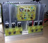
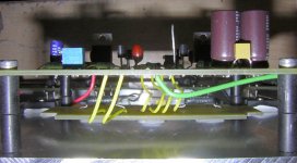
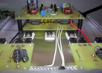
You can see here how I hooked up the PSU. I will do a proper star ground with a copper bolt and nuts once I mount everything in a case. For now they are just soldered. I thought this would be sufficient for testing.
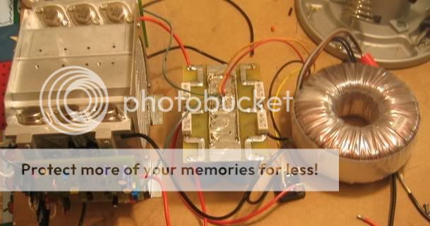
I used the same transistors as are called for on the BOM except for the outputs, which are MJ15003/4. They are all situated according to the printscreen on the boards, which I assume are correct since I haven't seen any posts to the contrary. The only transistor I'm not sure of as I type this is Q111 though I'm pretty sure I checked that with my meter before I soldered it up. I will double check that when I'm through typing this. I'll have to be sneaky about it though since my wife already asked me to lay of the electronics for the holiday.
I did check the main board first, but without knowing what voltages I should be getting, I was unsure whether or not I have it right. From the reaction I get when I hook it up to the outputs, I have to assume I'm don't.
Thanks again, Terry
I'm still havin' some difficulties finding a proper heatsink here in scandinavia short of watercooling.
But shouldn't one of these along with two fans per channel be enough?
Thermaltake cooler
But shouldn't one of these along with two fans per channel be enough?
Thermaltake cooler
An externally hosted image should be here but it was not working when we last tested it.
kmj said:I'm still havin' some difficulties finding a proper heatsink here in scandinavia short of watercooling.
But shouldn't one of these along with two fans per channel be enough?
Thermaltake cooler
An externally hosted image should be here but it was not working when we last tested it.
is the board that small?

MJ21193/4
Hi Jacco,
re post 3026 - MJ21193/4, Vbe(on)=2.2v.
How did you measure this?
I have just looked up Onsemi datasheet and it shows MJ21193 drawing 15amps at Vbe=2.2v!!!!!!
Minimum Vbe from the graph is about 550mV drawing about 200mA and at 650mV about 1500mA. These are all for Tj=25degC.
Since Vbe falls as the semi heats up then our ClassA output stage will have even lower Vbe for the same currents.
Please explain further.
My 15003 datasheet does not quote Vbe.
OK, Using two(different) regulated variable supploes here is what I measured in refrence to ground.......
Note: Bias is set to 150 mv across the emitter resistors and 8.9 mv offset... after 1/2 hour warmup.
Q-101 E .745
B 142.9 mv
C +36.07
Q-102 E .442
B 143 mv
C - 35.6
Q-103 E .617
B 0
C +35.9
Q-104 E .320
B 0
C -35.75
Q-105 E +36.5
B 35.95
C 0
Q-106 E -36.32
B -35.7
C 0
Q-107 E +37.05
B +36.5
C +1.29
Q-108 E -36.8
B -36.33
C -1.288
Q-109 E +.728
B +1.296
C +38
Q-110 E -.733
B -1.299
C -37.88
Q-111 E -1.06
B -.563
C +1.285
+ side OP device E 120 mv
B +.969
C +38.09
- Side OP Device E 140 mv
B -.735
C -37.89
Later tonight I will compare it with the other channel as I think a couple measurements may be off or perhaps I didn't have the probe in good enough contact. Ya got to be careful !
!
Mark
Note: Bias is set to 150 mv across the emitter resistors and 8.9 mv offset... after 1/2 hour warmup.
Q-101 E .745
B 142.9 mv
C +36.07
Q-102 E .442
B 143 mv
C - 35.6
Q-103 E .617
B 0
C +35.9
Q-104 E .320
B 0
C -35.75
Q-105 E +36.5
B 35.95
C 0
Q-106 E -36.32
B -35.7
C 0
Q-107 E +37.05
B +36.5
C +1.29
Q-108 E -36.8
B -36.33
C -1.288
Q-109 E +.728
B +1.296
C +38
Q-110 E -.733
B -1.299
C -37.88
Q-111 E -1.06
B -.563
C +1.285
+ side OP device E 120 mv
B +.969
C +38.09
- Side OP Device E 140 mv
B -.735
C -37.89
Later tonight I will compare it with the other channel as I think a couple measurements may be off or perhaps I didn't have the probe in good enough contact. Ya got to be careful
!Mark
Hi Terry,
After your visual check, go back & read my non-technical post 3023. Do the set up in small steps & you'll be OK, because you will spot any overheating / wonky voltages before they do any damage. Remember set your Vbe multiplier to minimum voltage before you connect in the output stage. i.e. less than 600mv per half or less than 1.2v total. If you can adjust to less than 1v total then better still.
I have just looked back at Delta Audio schematic ver 13-02-2005. It shows the upper leg resistor of the multiplier with a value of ???. What value did you use? The lower leg is 820r in series with 5k pot. The normal low bias label is beside the left pot. I think the right hand potin the diagram is the low bias setting. Can anyone confirm this? You close the extra contacts to bring in the second pot to adjust for ClassA Iq. Which way are you doing this?
What ????
ELFA sells Alutronic by the meter, and Arrow Nordic and Stig Walstrøm AB are swedish agents for Fischer....
Elfa?
I like my kidney where it is
But seriously, the only heatsinks i've seen there are REALLY expensive.

As for the others, do they sell to private persons also and not only companys? One of those tunnelsinks would be nice.
Terry,
Checking the PSU connections:
I asume that you Checked the PSU under some small load prior to connecting it to the board.
If not, do (some very basic) the following.
Disconnect rails from the board, if you have rails in the order of 50V calculate a resistance that will draw at least 0.5 amps, this would be 100 Ohms and need to be around 25W raiting or more.
Connect 1 such resitors from each rail to common (use alligators to ease the connection). You now should have equal voltage (one + and one -) from both rail. Voltage should read as expected. Resitors will get hot.
If this is not true you may have the polarity of one secondary reversed.
- Home
- Amplifiers
- Solid State
- Krell KSA 50 PCB