Thanks guys.
Ok, I have a few questions.
1) You can see in the pics the type of heatsink I plan to use on the drivers. Do you think these will suffice?
2) If you look just to the right of center in the first pick you can see the 2SC3955 bolted to the heatsink. Is this too far from the output transistors to do it's job?
3) The fan I purchased is 120V. It puts out a lot of air and is a bit noisier than I had hoped for. On my Hafler P500, there is a 120v fan that has two thermal switches which are bi-passed with 20W 150ohm resistors. As the heatsink heats up the switches open and send the current through the resistors. These are hooked in series and the switches open at different temps. Would this work for this amp?
If so, what temp switches should I use?
4) I used the terminal block as a way of securing the leads without grounding them to the heatsink. Do you think I could solder each set of three leads to eyelet connectors and then bolt them down? I worry about them moving around and somehow shorting out.
5) I only see one grounding point on these board and that is next to the input. It seems rather small. Is this the only point where they are grounded?
6) On the schematic I see R205 and C201 going to ground. are these necessary? Would I simply hook up from the output to the star ground?
They are what I have. Do you guys think they will be enough for this amp? I plan to hook them up like this.
Thanks again.
Blessings, Terry
Ok, I have a few questions.
1) You can see in the pics the type of heatsink I plan to use on the drivers. Do you think these will suffice?
2) If you look just to the right of center in the first pick you can see the 2SC3955 bolted to the heatsink. Is this too far from the output transistors to do it's job?
3) The fan I purchased is 120V. It puts out a lot of air and is a bit noisier than I had hoped for. On my Hafler P500, there is a 120v fan that has two thermal switches which are bi-passed with 20W 150ohm resistors. As the heatsink heats up the switches open and send the current through the resistors. These are hooked in series and the switches open at different temps. Would this work for this amp?
If so, what temp switches should I use?
4) I used the terminal block as a way of securing the leads without grounding them to the heatsink. Do you think I could solder each set of three leads to eyelet connectors and then bolt them down? I worry about them moving around and somehow shorting out.
5) I only see one grounding point on these board and that is next to the input. It seems rather small. Is this the only point where they are grounded?
6) On the schematic I see R205 and C201 going to ground. are these necessary? Would I simply hook up from the output to the star ground?
And what's the score with the CRCRC and the hefty 80V caps, heavy bias ?
They are what I have. Do you guys think they will be enough for this amp? I plan to hook them up like this.
Thanks again.
Blessings, Terry
Re: emitter resistors...
Hi stuart,
I'm hoping you are still sending some to me. I know I have already used others in this amp but I am planning on building another when Als boards are done.
Are you talking about adding a 16ga wire in addition to the ground plane? I am planning to tin the entire foil pattern with solder once I have the resistors and leads added.
I don't know what a MKP is. Could you explain this a little better and maybe give a recomendation for the part?
Thanks, Terry
Stuart Easson said:I'm about to head out to the post office to drop a batch in the mail so...
I wanted to reiterate, if there is anyone left out there from either PCB group buy that wants some of the now infamous panasonic 0r68/10w resistors for their amps, they just need to drop me a line. My email is enabled, so it isn't hard...
oh yeah, I want to see what the critters end up in, no more anonymous constructions ...send Mark or me a picture or post it here. Many have done so but there are those of you out there that are still in the closet about your constructions...
Happy building...
Stuart
Hi stuart,
I'm hoping you are still sending some to me. I know I have already used others in this amp but I am planning on building another when Als boards are done.
apassgear said:Terry,
Another thing... If I was building that kind of supply cap array for the PSU I would add a copper bus wire (maybe 16 ga) through the common plane joining all caps terminals and connections.
Have done this before and there is an advantage soundwise, specialy on bottom end.
Also... Adding a big MKP type (5/10u) to both rails (pralleling caps) will also make a big difference on smoothness. Ok, if your doing a CRCRC just do that on the last caps
Are you talking about adding a 16ga wire in addition to the ground plane? I am planning to tin the entire foil pattern with solder once I have the resistors and leads added.
I don't know what a MKP is. Could you explain this a little better and maybe give a recomendation for the part?
Thanks, Terry
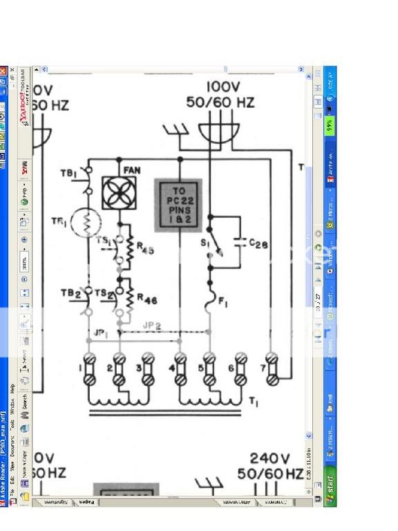
3) The fan I purchased is 120V. It puts out a lot of air and is a bit noisier than I had hoped for. On my Hafler P500, there is a 120v fan that has two thermal switches which are bi-passed with 20W 150ohm resistors. As the heatsink heats up the switches open and send the current through the resistors. These are hooked in series and the switches open at different temps. Would this work for this amp?
Hello Terry, try wiring the fan to one pair of the secondary outputs. The fan will run much slower and quieter, as it is an AC fan you should not have problems with the Hysterisis curve effect of a DC Motor. he fan will not draw enough current to unbalance the AC supply to the bridge rectifier.
BTW
MKP is a Metalized Polypropelene Capacitor.
Regards
Anthony
4) I used the terminal block as a way of securing the leads without grounding them to the heatsink. Do you think I could solder each set of three leads to eyelet connectors and then bolt them down? I worry about them moving around and somehow shorting out.
Hello Terry, this would be much better.
Regards
Anthony
still4given said:
Ok, I have a few questions.
3) The fan I purchased is 120V. It puts out a lot of air and is a bit noisier than I had hoped for. On my Hafler P500, there is a 120v fan that has two thermal switches which are bi-passed with 20W 150ohm resistors. As the heatsink heats up the switches open and send the current through the resistors. These are hooked in series and the switches open at different temps. Would this work for this amp?
If so, what temp switches should I use?
I prefer 12V DC fans, they are quieter, but that requires a 12V secondary or another small trafo. Building a PSU and circuit for a variable speed fan is very easy… I do mine on a 2.25x1.7 PCB including PSU. This way you can adjust the speed to what is requiered, in winter you may like a slower fan speed...
Looking at your setup I think you will need the fan ON all the time but you can add a thermo switch (through the secondary) to the fan circuit maybe some 75º C. DigiKey carries those, but don’t remember the part number, I could search for those if you want.
Coulomb said:Terry, you should add a 10,000PF Noise suppression cap across each side of the switch terminals.
Not only works as noise suppression but most importantly it will protect the contacts from arcing. I use anything at hand that is smaller than 0.1u. Usually .068u @ 400V or more.
Never had to replace a switch since I started to use these.
Here is the schematic showing the fan switch.
R45 and R46 call for 20w 150ohm.
I already have two 25w 150ohm resistors.
Would this work?
I am a little worried about using part of the secondaries from my xformer for my fan since it seems a little undersized as far as vA is concerned, especially since everyone else seems to using two xformers. Maybe I'm worrying for nothing.
Thanks, Terry
results and pics
OK Mark, thanks for the help. In the image below according to the posted (other) method-- looking at the transistor pins on the far side that face you-- the base is the pin on the left and the emitter is the pin on the right. I get a reading of .52 using my diode test mode on the DMM black on collector (case) and red on pin (MJ21193) and red on collector and black on pin (MJ21194). This is consistent with data sheets I have seen (note that the Onsemi DS does not indicate which pin is which).
I wonder what this .52 is supposed to represent?
Someone (ooops, look like it was you) said something about ohms. Using the DMM to read ohms I cannot get any reading between any pins and the collector; I know I used 200 ohm setting (yeah its too low...I know) and even a higher setting too but for some reason no setting would give me a valid reading. Anyway, it should have right?? Might have to check this again.
Mark A. Gulbrandsen said:With your meter on diode check range you will not get any reading beteen the collector(metal case) and the emitter. You will get 400 to 700 ohms typical between the base and collector(metal case) in one direction only. You will get that same reading or very close between emitter(pin) and base(pin) in one direction only.
Do the check and then report back and let us know which is which...... I know the pinout, but you do the test and so on and post.......
Thanks!
Mark
OK Mark, thanks for the help. In the image below according to the posted (other) method-- looking at the transistor pins on the far side that face you-- the base is the pin on the left and the emitter is the pin on the right. I get a reading of .52 using my diode test mode on the DMM black on collector (case) and red on pin (MJ21193) and red on collector and black on pin (MJ21194). This is consistent with data sheets I have seen (note that the Onsemi DS does not indicate which pin is which).
I wonder what this .52 is supposed to represent?
Someone (ooops, look like it was you) said something about ohms. Using the DMM to read ohms I cannot get any reading between any pins and the collector; I know I used 200 ohm setting (yeah its too low...I know) and even a higher setting too but for some reason no setting would give me a valid reading. Anyway, it should have right?? Might have to check this again.
An externally hosted image should be here but it was not working when we last tested it.
Pics of Front Panel
A word about my front panel.
I thought about this a lot. My amp will look kind of wacky like my other amps and preamps (see my www link below).
However, more to the point. I shamelessy stole styling cues from the KSA 50, and then the FBB series of amps. I'll use, as you can see, a countersunk name badge and the triangle of lights. This will be immediately recognizable as a krell clone due to these styling features, but the rest of the thing will be completely different.
Made by Frontpanelexpress.com, total cost was about $70.00. The badge part was over $20.00; very expensive and time consuming to design, but so very very relevant, don't you think?
I hate to ruin the surprise but Stewart wanted some pics. Since he has been so helpful here is a preview-- again against my better judgment. I feel bad about posting this early because I halfway think that all of you will laugh at this and hate it and I halfway think all of you will copy the idea...oh well you will see it eventually when its done.
An externally hosted image should be here but it was not working when we last tested it.

Coulomb said:Terry, you should add a 10,000PF Noise suppression cap across each side of the switch terminals. You should also add a CL-60 thermistor in series between the switch and the Fuse holder on the LIVE side.
Regards
Anthony
In the little schematic I posted from the P500 the switch shows C28 which is listed as .01mfd 1000V. Is this what yo are talking about?
They also have one across the bridge. Is that recomended?
Thanks, Terry
still4given said:
In the little schematic I posted from the P500 the switch shows C28 which is listed as .01mfd 1000V. Is this what yo are talking about?
They also have on across the bridge. Is that recomended?
Thanks, Terry
Caps across the rectifiers are snubber caps to prevent rectifier ringing.
Terry,
Your resistors are on the way...you should have them in the next couple of days...
The various small value caps around the mains input and bridge rectifier are a good idea, but not essential, they clean up the input from PG&E and reduce the possibility of mains borne interference.
The diode test tells you the forward conduction voltage of the diode formed by the junctions of the transistor. A reading between 0.5v and 0.6v would be expected for a forward biased junction, and no reading at all for a reverse biased junction. The C-E junction will not show any reading in either polarity.
Stuart
Terry,
Yes that is what I ment with the bus wire, just make a U and solder beside the cap terminals before you tin the ground plane.
It will work very nice if you tie the wire in 3 palces before sodering it, this is done by making small holes besides the wire and use a small gage copper wire for tying. But tin the bus wire first. You will need a hevier soldering iron in palce of what you use regulary for PCB work, applay heat over the bus wire.
Yes, as Anthony said, MKP is a metalized polyprop cap. >Even if you dont have provision for it now, try to test with and w/o and hear the difference, then you decide.
Re: drivers...
Thanks Stuart, It would be nice to have an addition to the wiki so as to have one place to refer to while bulding the KSA-500.
I will wait for your second toroid to be installed.
Stuart Easson said:k-amps,
The drivers, in this case a pair of to247 21193/4, are mounted on the 'main' heatsink, I have q111 clamped to this heatsink as well. There is a secondary heatsink that holds the last 6 pairs of outputs, which will be part of the same windtunnel, which ever ends up hottest will be the cold air end of the tunnel...
I used my variac to set the rails at 105 unloaded, they dropped to approx 80-85 at 800w RMS into 4ohm resistive. I didn't measure the mains voltage at this point, but I'm guessing it was suffering, as was the variac...I was feeling nervous about my 100v power supply caps...
So now I'm making a cable to run from the dryer plug, I can get 240v at 30a, should be more than adequate for prototyping purposes...
More later
Stuart
Thanks Stuart, It would be nice to have an addition to the wiki so as to have one place to refer to while bulding the KSA-500.
I will wait for your second toroid to be installed.
source for sinks
It is 3/4 of the Mystery amplifier
After almost 3 years of DIY I am convinced that the only place to get heat sinks and chassis' are ebay and surplus stores. And the trading post here of course.
apassgear said:Igreen/Terry
Where are you getting those nice sinks?
It is 3/4 of the Mystery amplifier
After almost 3 years of DIY I am convinced that the only place to get heat sinks and chassis' are ebay and surplus stores. And the trading post here of course.
Re: source for sinks
You lucky one!!!
lgreen said:
You lucky one!!!
- Home
- Amplifiers
- Solid State
- Krell KSA 50 PCB