pinkmouse said:Are you going to bring it along to our diy meet in July?")
If you diy meet is within 50 miles radius of Leedstown ! lol
I think I've got 2 good pairs of krell's I retested them all earlier (with a diode checker) but how to make sure?? I've got a few PNP's that I think are ok but only 2 NPN's.....
pinkmouse said:I could certainly do with something that runs slightly cooler!
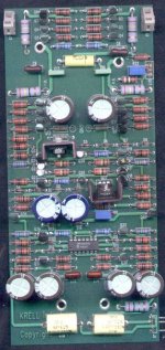
hmm...dunno about that it was getting quite toasty when I had it on test esp. the pre-driver transistors which arn't heatsinked. Also there are 2 x TO-220 packages on TINY heatsinks on the driver board I would of used bigger heatsinks e.g, like the ones on old comp motherboards or psus. No fans either, and the 10 x TO-3 cans on each channel are very closely spaced! I am musing to what originally caused the major fault I am trying to fix.....and whether it's likely to happen again!
Cheers have a good weekend I probably won't be on here till monday doing other things .....
Mark A. Gulbrandsen said:Sure would be nice if you could back engineer the driver board....
Thanks!
Mark
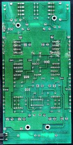
I'll try....I've had a look at it and it isn't as complicated as I thought most of the component side tracks are a ground plane. Check back for updates next week I'll probably do the PSU first.
BTW, how did you manage to sign on here in 1970 !!!
digitallake said:BTW, how did you manage to sign on here in 1970 !!!
Mark has powers*, the scale of which even mods can only speculate upon.
* Well, mostly a power bill we can't imagine due to his huge collection of Class A amps.
 I'm going to draw out the rest of the circuits this week I'll keep you all informed!
oh yeah, I won't wait until someone asks the chip is MPQ6600A1 (Motorola) good luck
maybe....? http://www.diyaudio.com/forums/showthread.php?threadid=19547&goto=nextoldest
maybe....? http://www.diyaudio.com/forums/showthread.php?threadid=19547&goto=nextoldest
Attachments
Hi,
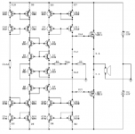
As far as I can see the chip is a balanced input stage, or preamp the bias section is in the next block of the circuit but I haven't started the schematic yet that's just looking at it and making assumptions....check back soon for updates should have it complete within the next couple of days.
Cheers, Jim
Hi,
are q1&7 the amplifier in that schematic? All else seem to be mirrors, but even they are half of mirrors.aparatusonitus said:IMHO the basic topology is based on current conveyor like this one below...
enjee said:Obviously,the basic topology is NOT based on current conveyor
The input chip is a 4 BJTs or JFETs,I think
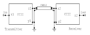
The input chip consist two NPN's and two PNP's, perfect for input current mirrors. And if a Krell's CAST topology is used, then we have the basics, no global NF only lokals, just throw in some emitter resistors. CAST connection should look like this...
Attachments
AndrewT said:Hi,are q1&7 the amplifier in that schematic? All else seem to be mirrors, but even they are half of mirrors.
Well, I don't know that, but you can fit in as much mirrors as you like, with gain or not, I think...
- Status
- This old topic is closed. If you want to reopen this topic, contact a moderator using the "Report Post" button.
- Home
- Amplifiers
- Solid State
- Krell KAV 250a deader than a dodo