A class H amplifier would have multi-tiered DC power supply - the simplest being at least two tiers. Opening up the case and measuring the supply voltages will probably tell you if it is or not. On the other hand, if the manual says the amplifier is class AB, then it probably is.
The choice of how much filter capacitance goes into an amplifier is a manufacturer's choice, and dependent to an extent on the amplifier design. Having a large capacitance allows for a larger amount of transient energy to be provided by the power supply, but ultimately continuous current demands (due to low impedance speakers) must be supplied by the transformer - so check the size of the transformer in the amp, that is the more important factor...
So, can your amplifier drive 2 ohms? Yes, it can. But it gets hot. So ultimately, probably not a good idea to drive it that way.
Cheers
thanks clem_o
so sorry friend don't know whats the meaning of tiers.
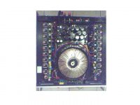
using the fluke multi tester, the voltage goin to power amp module ( board ) is +126 Volts and -126 volts per channel.
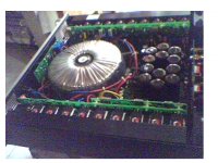
yes there are other voltages from the toroidal transformer.
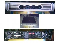
the amp is quite heavy for the size.
here's the pic of the amp mate.
so sorry friend don't know whats the meaning of tiers.
using the fluke multi tester, the voltage goin to power amp module ( board ) is +126 Volts and -126 volts per channel.
yes there are other voltages from the toroidal transformer.
the amp is quite heavy for the size.
here's the pic of the amp mate.
Attachments
Howdy,
Look at the power supply and determine where the LARGE capacitors go. Are they all paralleled together, and is that where the +-126V comes from? Or are there LOWER voltages from the power supply with just as much filtering, i.e. maybe something like +-75V
If your main power is ONLY the +-126V, then the amp isn't class H.
There will be other (lower) voltages, but these will probably be low-current and not heavily filtered, i.e. to supply the fan circuit, to power up the low-level electronics (op-amps) etc...
Cheers
The 85-0-85 is probably used for the front-end of the amplifier.
The twin 43-0-43 volts is interesting - it points to a potential for class-H operation, i.e. maybe the transformer is used for another model that is class-H.
Try to look very well at how the two 43-0-43 volt secondaries are connected. My guess would be:
43 - to bridge rectifier
0 - no connect
43 --
|---- to gnd
43 --
0 - no connect
43 -- to bridge rectifier
With this, you get a total of 86-0-86, which would translate to your +-126 DC voltage.
Cheers
Ok, I think I see what they are doing, silly me.
Your filter capacitors are rated at only 63 volts. What they are doing is using the center tap of each 43-0-43 volt winding to ensure that a stable "Center" voltage exists for the filter capacitors. Your filter capacitors are then in "Series" across the full 126 volt potential, running smack right at their voltage limit. Dangerous and bad for long life...
So that "120,000uF" of filtering is a 'spechmanship' joke. The total filtering is only 60,000uF effectively, 30,000uF per rail.
Cheers
jayrjoe said:2SC 5200
2SA 1943
clem_0 ive noticed that this amplifier has exactly the same output transistors with my Konzert K10 Power Plant amplifer, only the K10 has 20 output transistors per channel
the alpha 1200 has only 18 transistors per channel
The C5200 and A1943 are popular power transistors from Toshiba. They are rated fairly high (in fact are pretty much the highest overall spec rating for BJTransistors currently), so it is not surprising that several amps will use the pair.
Given that you have spotted the complement (A1943) in the amp, then your topology is probably an EF-type complementary output design, running class AB or B (with the latter preferred, actually, since there is no sonic gain to running the outputs in AB mode).
Cheers!
clem_o said:Ok, I think I see what they are doing, silly me.
Your filter capacitors are rated at only 63 volts. What they are doing is using the center tap of each 43-0-43 volt winding to ensure that a stable "Center" voltage exists for the filter capacitors. Your filter capacitors are then in "Series" across the full 126 volt potential, running smack right at their voltage limit. Dangerous and bad for long life...
So that "120,000uF" of filtering is a 'spechmanship' joke. The total filtering is only 60,000uF effectively, 30,000uF per rail.
@@@ so u mean this is not a good amp design mate? very silly design? you said that its dangerous and bad for long life, u mean when use for long term at high power levels.?
what could i possibly modify to make this amp more stable and good one.?
from the manual it has a lot of protections....
thanks mate
best regards
")
Hi jayrjoe,
The amplifier circuit itself is probably ok, given the number of protection circuits built in (I won't comment on how good or bad it sounds, as I've never heard it).
From the looks of it, the power supply voltages are too close to the ratings of the capacitors. You'd want some voltage rating margin, the minimum would be to use 75V capacitors instead of the 63V. But this would mean larger physical size, so replacements may not fit - you'd have to use something with slightly less capacitance.
If you go with 8,000uF 75V capacitors, this should be ok - it will results in a more "saggy" power supply, causing a slight drop in total power capability of the amp - this is probably good so that your amp doesn't get pushed so hard. Overall a contribution to longer life for the whole thing...
Cheers
ps: does it have an power input voltage selector? If it has a 240V option, set it there.
jayrjoe said:clem_o just want to clarify the meaning of this...
output topology --- EF - type complimentary output design
Educated guess. EF- Emitter Follower.
This topology is very popular, there is arguement that this is the 'best' output topology, combining lower distortion (due to complementary pairs providing symmetry), and a wider bias voltage tolerance for thermal stability.
Cheers
oh im so sorry clem_o
i had a very big mistakes.
@the 1st secondary supply 43 - 0 - 43 volts(13A) = going to the capacitors...
then from the output connector of caps going to the main amp board +-126 volts ( left channel)
@the 2nd secondary supply 43 - 0- 43 volts(13A) = going also to the capacitors...
also from the output connector of caps going to the main amp board +- 126 volts (right chanel)
@the 3rd secondary supply 86 - 0 - 86 going to the bridge rectifier
@the 4th secondary supply 0 - 22 Volts going also to rectifier
my apology mate, so sorry to confused you.
for my taste, well it does sounds good, very good bass transients even at high power levels.
my only concern that it gets hot even driven for few minutes.
maybe the heatsinks are smaller to the size of the trainies, that's why heatsink temp easily goes high, and from your comments, the amp has lower power ratings to the driven speakers.
no voltage selector mate, only 220-240 volts fixed
my only concern that it gets hot even driven for few minutes.
maybe the heatsinks are smaller to the size of the trainies, that's why heatsink temp easily goes high, and from your comments, the amp has lower power ratings to the driven speakers.
no voltage selector mate, only 220-240 volts fixed
Seems it may be using a swinging power supply configuration to drive the speaker. The approach has various incarnations, including the one used by QSC...
Suggest 'leave it be' and don't demand too much power from it. As rlg suggested, maybe you can up the cooling fan a bit to get more air flow instead...
Cheers!
Suggest 'leave it be' and don't demand too much power from it. As rlg suggested, maybe you can up the cooling fan a bit to get more air flow instead...
Cheers!
- Status
- This old topic is closed. If you want to reopen this topic, contact a moderator using the "Report Post" button.
- Home
- Live Sound
- PA Systems
- Konzert Amp & Speakers Website