Well, now's the time for you to come to terms with my stupidity. My parents did it, my grandparents did it and now its your turn.
So I'm trying to make sure I am utilizing the "common mode" concept for the transformer. My standard grounding methodology it to run a separate line to the PSU and first stage grounds for each ground. So, that means that the 4uF, orange lead, yellow lead and the three 50uF caps will all have a ground lead running to a single-point ground near the 4uF cap.
If you're saying that I can use this scheme and still realize the gonzta / gozouta of the bottom "resistor" of the common-mode choke, then that's good. If, however, you're suggesting that I need to ground using a "ground buss" style to realize the true AC impact of the common-mode choke, then I'm a bit confused.
Realize now that you've made a mistake in communicating with me. Mrs. Annan realized that a little too late and look where that got her.
Kofi
OK, Here is how to wire it, from your rectifier. The high voltage out goes to the + of the 4uf cap. Either the wire from the 2 SS diodes if you are using them. or the CT of the high voltage winding goes to the - of 4uf cap.
The red wire of the choke goes to the + of the 4uf cap and the orange wire goes to the -
Nothing else gets connected to the 4uf cap.
Connect the violet wire to the + of the 50uf cap. B+ starts here.
Connect the yellow wire to the 50uf -. This is your star ground point. Anything from the rest of the Amp that needs a ground goes here. Not to the 4uf cap it lives in a little world of it’s own.") ...John
...John
The red wire of the choke goes to the + of the 4uf cap and the orange wire goes to the -
Nothing else gets connected to the 4uf cap.
Connect the violet wire to the + of the 50uf cap. B+ starts here.
Connect the yellow wire to the 50uf -. This is your star ground point. Anything from the rest of the Amp that needs a ground goes here. Not to the 4uf cap it lives in a little world of it’s own.
...JohnYEAH! YEAH! YEAH!
That's what I'm talking 'bout!
Two realizations have happened here. One, I realized that this configuration is necessary to employ the common-mode choke properly. Two, you realized that I'm dumber than you originally thought possible.
Thanks so much for explaining this. I know I can be trying and I appreciate your patience.
I finished the casework on the second monoblock this morning, so I'll be wiring a bit tonight and this week. I'll post my progress as it happens.
Thanks again for all your help.
Kofi
OK, just to muddy the waters a bit more. We’re not actually using this choke common mode. Why you ask? Well two reasons, A common mode choke is used mostly to filter noise and garbage off the line, not for heave duty rectification duty like you need here.
And when you wire the choke you have parallel (dots on the same side) like I described above you get according to Jack 20h which is a lot. If you wire it common mode (one dot right one dot left) most of the reactance cancels out and you get a few mh
If you look at the filament supply you sent you see that the common mod choke is at the end after all the hard work has been done and is just a noise filter.
And no you do not need to add a common mode filter to the B+. It is already far better then most similar amps. Time to leave more then well enough alone…John
OK-- so we're wiring some today and I think I have the 300b filament circuit together. It appears that this is a "floating" supply and I wanted to check and make sure I was getting ~4.8VDC before I hooked up the 300b and I got about 13VDC.
I'm guessing that this is because:
a. the supply is "floating" and
b. I have not hooked up the filament supply to the 300b and the circuit is unloaded with no (or really, really little) current flowing
Can anyone confirm that this is the case? Would running this across a 2-3 ohm resistor better mimic how it will perform once the 300b is plugged in? Should the negative filament supply actually be referenced to ground and I"m just misunderstanding?
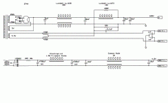
PSU schematic attached for reference.
Kofi
I'm guessing that this is because:
a. the supply is "floating" and
b. I have not hooked up the filament supply to the 300b and the circuit is unloaded with no (or really, really little) current flowing
Can anyone confirm that this is the case? Would running this across a 2-3 ohm resistor better mimic how it will perform once the 300b is plugged in? Should the negative filament supply actually be referenced to ground and I"m just misunderstanding?
PSU schematic attached for reference.
Kofi
Attachments
An inductive filter will peak charge if you don't load it. The output will start to rise above the expected value below what's called the critical output current, which depends on input voltage, inductance, and line frequency. No biggie, but if you want to know the voltage under your working conditions, you have to load ithe filter similarly. Once you're above the critical current, the output voltage is pretty constant. It's a good check to do the load test before you risk your tubes to make sure you have enough inductance for your proposed load.
Kofi Annan said:[B Should the negative filament supply actually be referenced to ground and I"m just misunderstanding? [/B]
No separate ground reference. The path to common goes through the resistors beneath the cathode/filament. Also, the polarity of the filament supply can go either way. See if one sounds better. Likely you won't hear much difference.
Sheldon
Thanks!
I added a 6-ohm resistor as a load and it wound up right at 5V (maybe 5.03 or so), so we're good. Also, the PSU is up and working. Its showing well over 700VDC, but that's with no tube in place and, again, no real current being drawn.
So, here's a question-- what's the best resistor value to drain the caps with? I used the 6-ohm that I had laying around and gor quite a snap when I tried to drain the caps.
Kofi
I have a cheep 10K 10W cement resistor with the ends of some old meter leads attached. A 10K will drain the caps pretty quick but will get hot at real high voltages. 700V will be 70ma or 49 watts but only for a few seconds. On second thought something like 47K will be 15ma at 10.5W. It will just take 30 or 50 seconds or so to drain down…John
Good news! Thanks!
OK-- so much like every project, I realized that I did not order some parts that I need. I went ahead and ordered them today, but they won't be here until next week.
The parts I'm missing are the 33K resistor and the 2.2uF cap shunting the elevated D3a filament supply to ground (see PSU schematic attached earlier). I'm wondering if I could get away with simply using the 6.3VAC winding straight to the filaments for now and then elevate the supply once the parts arrive.
If I wanted to to this, would I have to reference the heater supply to ground somehow? I'm guessing I could do this through a couple of resistors, but I'm not sure.
Can you help with the specifics here?
Kofi
"OK-- so much like every project, I realized that I did not order some parts that I need. I went ahead and ordered them today, but they won't be here until next week."
That never happens to me>
As to referencing the heater to ground. If you mean the 5V for the 300b, that gets done by the cathode resistor. The 6.3 in your schematic has a ground ref…John
That never happens to me>
As to referencing the heater to ground. If you mean the 5V for the 300b, that gets done by the cathode resistor. The 6.3 in your schematic has a ground ref…John
Kofi Annan said:Good news! Thanks!
OK-- so much like every project, I realized that I did not order some parts that I need. I went ahead and ordered them today, but they won't be here until next week.
The parts I'm missing are the 33K resistor and the 2.2uF cap shunting the elevated D3a filament supply to ground (see PSU schematic attached earlier). I'm wondering if I could get away with simply using the 6.3VAC winding straight to the filaments for now and then elevate the supply once the parts arrive.
If I wanted to to this, would I have to reference the heater supply to ground somehow? I'm guessing I could do this through a couple of resistors, but I'm not sure.
Can you help with the specifics here?
Kofi
Yes, you can skip the voltage divider and cap for now and just reference the D3a fillament directly to ground. The voltage lift may reduce noise some, but is not a safety or reliability issue.
Sheldon
Thanks!
But to clarify-- since the D3a has a non-center-tapped heater at pins 4 and 5, wouldn't I actually ground one leg of the 6.3VAC supply and pin 5 while connecting the other supply leg to pin 4?
I know that the supply needs to see 6.3V, but I don't see how it can in AC without one supply leg grounded.
Take a deep breath, now.
Kofi
Kofi Annan said:Thanks!
But to clarify-- since the D3a has a non-center-tapped heater at pins 4 and 5, wouldn't I actually ground one leg of the 6.3VAC supply and pin 5 while connecting the other supply leg to pin 4?
I know that the supply needs to see 6.3V, but I don't see how it can in AC without one supply leg grounded.
Take a deep breath, now.
Kofi
You could do it the way you describe. But you already have a "virtual" center tap formed at the center of the two 470R resistors. Just connect that to ground.
All the filament needs to heat up and glow the nice red color is a voltage potential of 6.3V from one end to the other (pin 4 to 5). To heat up doesn't need to be referenced to ground at all, as the current flows between one end and the other. No current flows to ground However if it "floats" relative to the other tube components, you're gonna get hum, as there is nothing to keep it stable relative to the cathode. Ideally, you have it (either end, or the center, as in your supply) referenced to a potential about 30V above the cathode. Next best is referenced to ground. In either case, no current from the filament flows to ground - well, a tiny amount, a few stray electrons here and there. But if you don't drain off those stray charges, the filament will drift around, relative to the cathode.
Sheldon
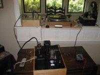
Alright! The first monoblock is alive!!
It sounds awfully nice with just one speaker, but I think I won't know the true nature of the sound until the second channel is built. Its running at 60mA but only about 310V from plate to cathode of the 300b (should be ~350V). This may not be much to worry about given the margin of error in tubes, but I think I may try and find the reason for the lower voltage.
Thanks for all the help! I'll start building the second block tomorrow, but I probably won't have it finished until next weekend. I'll post some under-the-hood photos later.
Kofi
Attachments
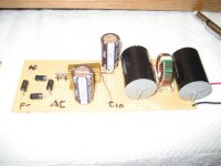
Kofi Annan said:Here's a photo of the perf board I mocked up for the 5V heater supply. Should I move the wirewound 2R5 resistor off board and heatsink it to the chassis, or will it be OK like this?
Kofi
You're only dissipating about 3 watts, so it doesn't have to be heatsinked (though that never hurts). But you should space it a few mm off the board and not put it beneath any heat sensitive components.
The wire on that CMC looks a little wimpy to me. Have you checked that the resistance is ok (no significant warming).
Sheldon
The CMC is rated at 2.5A so it should be OK. I'll check the resistance and report back.
So, I'm getting 210V at the 300b grid (also the D3a anode, of course) and 277V at the 300b cathode, which is causing me to run the 300b a little low. The B+ is dead on and the plate of the 300b is running at 598V, nearly perfect.
So, in essence, the the 300b is seeing 322V instead of 350V and the grid bias is at -67V instead of -72V. I have cranked the current to 62mA for the 300b and there's still no appreciable change in voltage, so I'm thinking that maybe I've got a bad resistor somewhere.
At least the B+ is good, so I'm thinking that I just need to find the faulty resistor (probably one of the 100R / 10R / 10R trimpot gigs).
Any thoughts?
Kofi
- Status
- This old topic is closed. If you want to reopen this topic, contact a moderator using the "Report Post" button.
- Home
- Amplifiers
- Tubes / Valves
- Kofi Annan in: "Kofi Makes a 300b DRD... and You Get to Help!"