Mooly said:Just a suggestion/idea,
Try 0.1mfd across zeners only and a 100mfd/50volt soldered directly across pins 7 & 4.
Not sure what pins those are? Edit: Ah, the pins on the OP, dohh!
I used to have single 0.1µF poly-something caps across the D1,D2 zeners, but AD797 spec sheet says to use 4.7µF + 0.1µF ceramic. However, the 100µF cap made an absolutely huge difference! (PS: I actually put the caps right on the OP's Vcc pins, although it would have been easier to put them physically just across the zeners. I suppose for lower capacitance it's better the closer you can get.)
Ragnwald said:Hi guys
I´m following this tread with interest.
Think you mean µ, when you spell m or u?
Press Alt Gr when you write m, and you get µ.")
Hi Ragnwald!
Alt Gr + m only works with the Swedish keyboard layout, it seems.
Hi Patrik and Ragnwald,
Actually on the IC is best. Circuit board "print" and component legs posses inductance which at higher frequencies negates the effect of the cap. And come to think of it electrolytics also posses self inductance and this is why you see them parralled with a smaller 0.1 thing ( Apologies to Ragnwald) - I did try, pressed a lot of buttons-- thought I might break something.
So yes, decouple the zeners as they are "noisey" devices, and add a small 0.1 across the IC as well as the electroylitic.
Actually on the IC is best. Circuit board "print" and component legs posses inductance which at higher frequencies negates the effect of the cap. And come to think of it electrolytics also posses self inductance and this is why you see them parralled with a smaller 0.1
thing ( Apologies to Ragnwald) - I did try, pressed a lot of buttons-- thought I might break something.So yes, decouple the zeners as they are "noisey" devices, and add a small 0.1 across the IC as well as the electroylitic.
I decided to press on with modding, as I received some MJ15003 transistors.
However, when checking one channel with the new dumper transistors the amp went into osciallation, and blew one of the rail fuses.
The original devices are "RCA 17556" which I have great difficulty in getting any sort of specs sheets for online.
I was under the impression that the MJ15003 was a drop in replacement in the 405 and 405-2.
Of course, the device I ordered from Farnell was a "MULTICOMP MJ15003" and the printing on the device itself says "MOSPEC MJ15003", so heaven knows what I actually got! Counterfeit?
Edit: http://www.mospec.com.tw/
Update:
I installed new MOSPEC MJ15003 on the right channel, and ON MJ15003 on the left channel. Stereo imaging was so-so. After some loud playing the right channel sounded crackely (I first feared the speaker was broken). Both MOSPEC transistors measured correctly, but the right channel broke into and out of oscillation on the negative period. After replacing them with "ON" the problem was fixed, and low end grip and stereo imaging improved.
So better stay away from "equivalent" MJ15003... (I'll complain to Farnell)
Apart from that I have installed 1W zeners, and 2W 1.5kOhm resistors feeding the OpA.
I found out that AD797 sounds great but behaves really badly at times during power up and down (worst is power down and up too quickly). It can latch even after power is fully up. Cannot use for that reason.
I got the OPA627 finally, and it really does sound great. Behaves very well too during power up and down. Shame I can't A/B with AD797 due to the problems.
Mooly said:Hello Patrik,
Good point, but things seem perfectly OK now with the "ON" versions!
I altered the grounding so I just re-route the large signal ground to the 'speaker return post. The rest is standard. (Although I'm looking to lift the input negative from chassis some time soon.)
Sound is very good now using OPA627, but even better with AD797 I believe. (I just know I never heard anything like it..) Gotta make that one work..
OPA627 is just a little bit too polite for me. Perhaps the OPA827 is the answer.The biggest single change so far has been adding the two 100µF over the zeners. I have yet to analyze exactly why. I suppose that even if the zeners work well, the best Z to ground would be either 10R or through the chassis. So big caps makes sense.
Edit: I tried using a single 100µF over pins 4 and 7, but it didn't improve sound as much as two caps to ground did.
Also have to decrease current limiting.
Hmm.. After a whole day of no modding the amp sounds better, with the OPA627 in place. Big caps around the OpA improving? Better mains power today? Imagination?
I built a mock-up of the input stage in order to test OpA behaviour. Strangely the AD797 exibited a large increase in output over about 200kHz, centered on 1MHz. About 6dB. I also found that the TL071 dropped off at around 70kHz, with the gain of 15. (All on it's own, without the 405's 50kHz low pass.)
I built a mock-up of the input stage in order to test OpA behaviour. Strangely the AD797 exibited a large increase in output over about 200kHz, centered on 1MHz. About 6dB. I also found that the TL071 dropped off at around 70kHz, with the gain of 15. (All on it's own, without the 405's 50kHz low pass.)
Latest mods (summary: DON'T bypass C2 with 100nF!):
Yesterday:
Lowered gain: 1.5V instead of 0.5V for full power.
Added 100nF over C2, as per recommendation by B. Ludwig. Runied the sound! Micro detail gone. Gray. Fatiguing.
Today:
Removed 100nF from C2 and replaced C2 with B.Ludwig's [3bi] mod, the double DC biased caps mod. Did this to one channel.
http://www.geocities.com/ResearchTriangle/Lab/6722/405mods4.txt
Used this mod in right channel, together with left channel from yesterday. All detail was on the right. The left side was almost "dead" in sound stage. Sound stage tilted well over to the right.
Removed 100nF from C2 on left channel. Left channel now lively again! Sound stage now off-center towards the left.
Implemented mod [3bi] on the left channel. Sound v. nice again. Sound stage centered. Too late to crank it up, though!
Just for the information, there is a later document from Bernd Ludwig, http://www.dc-daylight.ltd.uk/Valve-Audio-Interest/QUAD/QUAD-405-Modification/405_Qw_7.pdf
Mooly said:Hello Patrik,
I'm still following it all. Just battling with Windows at the moment, reinstall may be on the cards
Glad someone is interested!
BTW, didn't mean to hijack your thread. It sort of happened since anyone building a 405 from scratch will have to think about all the various tweaks available, and power supply etc, as well.
Do you have a schematic for your 405 kit? (Verified against the actual PCB)
That would help in fault searching!
Forgot your exact problem now, but I assume you used a dual power supply AND hooked up the mid (0V) to the amp? (three wires in total) It won't work without 0V line from power supply, even if it may look like it might from the various connections!
Windows:

RogerGustavsson said:Just for the information, there is a later document from Bernd Ludwig, http://www.dc-daylight.ltd.uk/Valve-Audio-Interest/QUAD/QUAD-405-Modification/405_Qw_7.pdf
Thanks for the info!
I had missed that one, and it has at least one useful correction too! (C2 does influence sound.)
Hej Patrik!
There are even more ways to treat C2. Will have to check some old E-Mails at home. I just remember the use of a plastic film capaictor for C2, 2.2µF or so.
According to Bernd Ludwig, reducing the gain of the integrated circuit is a main point in his modification. That is as far as I came with my Quad 405-2 before they showed other signs of ageing. That is also why I am looking for building new PCBs from scratch, removing all components that are not strictly necessary.
Roger
RogerGustavsson said:Hej Patrik!
There are even more ways to treat C2. Will have to check some old E-Mails at home. I just remember the use of a plastic film capaictor for C2, 2.2µF or so.
According to Bernd Ludwig, reducing the gain of the integrated circuit is a main point in his modification. That is as far as I came with my Quad 405-2 before they showed other signs of ageing. That is also why I am looking for building new PCBs from scratch, removing all components that are not strictly necessary.
Roger
Yes, the "Platinum Ear" version is with a large foil cap, and altered resistance value.
I didn't expect much from replacing a bipolar 'lyte cap (if it's even bipolar, I'm not sure) with two cheap electrolytics biased to -15V in the middle. I was totally wrong! I don't think you need golden ears to appreciate the difference. Any old non-deaf ears should do!
Well, that was a big surprise!
Mooly said:Hello Patrik,
Think I'm back in the game now. Reinstalled from a 2 1/2 week old backup. Touch wood
Glad to hear it!
Some interesting text and links here about caps:
http://stephan.win31.de/capdist.htm
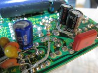
Here is a photo of the latest mod, the biased double electrolytic C2:
Attachments
Some nice links in there. When you do any changes give it time. Listen for a day or two. I know it's easy to alter something and you are that worked up it's all a bit of an anti climax when you listen for the first time.
Isn't C2 an integrator, it's job being to "remove" audio and thus provide a DC reference of the output. I find it hard to believe it's that critical subjectively. What would make a big difference though is where ( those grounds again ) it is returned too. It has to go to the input ground so as not to "add" any unwanted signal to the input stage.
Isn't C2 an integrator, it's job being to "remove" audio and thus provide a DC reference of the output. I find it hard to believe it's that critical subjectively. What would make a big difference though is where ( those grounds again ) it is returned too. It has to go to the input ground so as not to "add" any unwanted signal to the input stage.
- Status
- This old topic is closed. If you want to reopen this topic, contact a moderator using the "Report Post" button.
- Home
- Amplifiers
- Solid State
- Kit building Quad 405 Clone