I have tried some different OP amps in the 405-2.
I bought OPA604 and AD797, hoping that OPA604 might give a flavour of what OPA627 is like at lower cost.
I didn't like the OPA604 at all. Sounded very rolled off. (Although I'm sure it will measure flat, of course.)
I much preferred the TL071, which is the standard OP amp in the 405-2.
I then tested the AD797, and it sounded a lot more like the TL071. Possibly better. Drawback is the higher DC on the speaker terminals due to the bipolar inputs of the AD797. It's now about 5mv instead of 0.5mV, so still very acceptable.
Decoupling at the OP-amp's power pins are 4.7uF and 100pF. The 100pF should have been 100nF, so I'll have to re-evaluate after getting the correct caps.
The TLO71 is surprisingly capable. When I changed the opamps in my MicroMega Stage 2 CD player I went from original NE5534 to TLO71. Excellent, kept it like for several years. Now use an OPA604 as the I/V convertor and an AD845J as the output buffer/filter. This gave me the most "analogue" type sound -- it's wonderful.
It always surprises me in audio how it's the unmeasurable that really make the difference sometimes.
As always, it's what works for you in your application and what gives the sound you are looking for")
It always surprises me in audio how it's the unmeasurable that really make the difference sometimes.
As always, it's what works for you in your application and what gives the sound you are looking for
Mooly said:The TLO71 is surprisingly capable. When I changed the opamps in my MicroMega Stage 2 CD player I went from original NE5534 to TLO71. Excellent, kept it like for several years. Now use an OPA604 as the I/V convertor and an AD845J as the output buffer/filter. This gave me the most "analogue" type sound -- it's wonderful.
It always surprises me in audio how it's the unmeasurable that really make the difference sometimes.
As always, it's what works for you in your application and what gives the sound you are looking for
I found the AD845 and the OPA604 unsuitable for me in similar ways -"rolled off". Or "muffled" to use a better word!
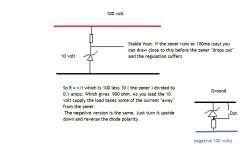
However I'm still wondering if the operating conditions were unsuitable. I didn't yet change the 3.3kOhm resistors in the Vcc lines. Perhaps they need to be lowered a bit. (The zener in the positive line should shunt off any excessive current. I don't understand how the negative line works..)
I did check the voltages, which were OK. But perhaps more current need to be shunted off to improve regulation?
P.S: Any opinions about the AD627?
Mooly said:Hello Patrick,
The negative zener will work as per the positive one
Just the normal Quad 405- 2 you mean.
Silly me! I just didn't see that zener in schematics!
Yes, it's a pretty normal 405-2. Still.
I'm itching to move C8, but I don't want to do all other mods, and I'm not clued up enough to do only parts of them!
Never tried the AD627. You can always use the offset null on any single opamp to get a true zero output.
Moving C8. Is that the 120 pf cap in the "error sensing bridge" ?
Move it where. It's one of the most vital points of the whole design. The original Quad concept used a resistor bridge ( I think ! ) but the losses were deemed to great so an inductor was substituted for one of the resistors, and to maintain the "bridge balance" a cap was used for one of the other resistors in the bridge.
The maths is way beyond me to analyse that one
Have to go now
OK, the 3.3kOhm lines will draw 10.6 mA, which is close to the AD797's max requirement, so I'll lower the resistor values a bit. 2.2k or 1.8k should do it. Just hope the zener can cope with shunting almost 20mA (for some OPs). 20mA * 15V is 300mW.
EDIT: The BZY88C zener seems to be a 500mW part, for those who want to know. Safest to go with 2.2kOhm then I think.
EDIT: The BZY88C zener seems to be a 500mW part, for those who want to know. Safest to go with 2.2kOhm then I think.
Remember to allow for any output current from the opamp itself. Just quickly looking at the Quad circuit it works into aprox 4 k ohm so that can add another 2 or 3 ma depending on output.
Trial and error can be useful
Work backwards, say 50 volt rail and 15 volt zener. That gives 35 volts to lose on the resistor. A 500mw zener, I =W/V which is 33ma. That's with no load on the zener. So the resistor is just over 1 k. Thats the lowest you can use drawing no current from the zener.
You don't need 33 ma, lets say 10.5ma worst case for the IC and 5 ma worst case as an output current. That give 15.5ma, now allow a little for the Zener under that condition, say 5 ma. So we have 20.5ma through a resistor dropping 35 volts. Thats 1.4K. A 1.5k would be fine at preferably 2 watt rating.
Mooly said:Remember to allow for any output current from the opamp itself. Just quickly looking at the Quad circuit it works into aprox 4 k ohm so that can add another 2 or 3 ma depending on output.
Trial and error can be useful
Work backwards, say 50 volt rail and 15 volt zener. That gives 35 volts to lose on the resistor. A 500mw zener, I =W/V which is 33ma. That's with no load on the zener. So the resistor is just over 1 k. Thats the lowest you can use drawing no current from the zener.
You don't need 33 ma, lets say 10.5ma worst case for the IC and 5 ma worst case as an output current. That give 15.5ma, now allow a little for the Zener under that condition, say 5 ma. So we have 20.5ma through a resistor dropping 35 volts. Thats 1.4K. A 1.5k would be fine at preferably 2 watt rating.
Thanks for your calculations!
I used 2.2k. Actually 6.8k in parallel with the original 3.3k as I didn't have any resistor above 250mW rating.
It made a big, positive, change to the sound -still using the AD797.
I didn't especially allow for output current (apart from an almost 2x margin), but don't want to stress the zener by going lower (in case I go back to TL071). I'll replace the zener and use 1.5kOhm, changing both at the same time instead.
I also put two 1000uF caps directly on the boards' power rails. (I already had added 2x100uF). Another improvement in sound. Likely made larger since I still use the push connectors for all original cabling. Should also help channel separation.
Yes, C8 is in the bridge. In theory it should be moved a bit to be in the optimal position, according to:
http://www.dc-daylight.ltd.uk/Valve-Audio-Interest/QUAD/QUAD-405-Modification/QUAD-405-Mods.html
However, as good as things sound now I'm not in a hurry to try that mod!
I still have several other mods lined up.
I'll post some pics for those interested.
The BZV85 series zeners may be more suitable (1.3 watt)
http://cpc.farnell.com/jsp/search/b...ensearch_003&Ntt=zener&Ntx=&_requestid=289798
If you are adding caps make sure they don't feed into the signal ground. This will couple noise etc, which is worse under load, into the signal stages.
http://cpc.farnell.com/jsp/search/b...ensearch_003&Ntt=zener&Ntx=&_requestid=289798
If you are adding caps make sure they don't feed into the signal ground. This will couple noise etc, which is worse under load, into the signal stages.Patrik Floding said:
I found the AD845 and the OPA604 unsuitable for me in similar ways -"rolled off". Or "muffled" to use a better word!
However I'm still wondering if the operating conditions were unsuitable. I didn't yet change the 3.3kOhm resistors in the Vcc lines. Perhaps they need to be lowered a bit. (The zener in the positive line should shunt off any excessive current. I don't understand how the negative line works..)
I did check the voltages, which were OK. But perhaps more current need to be shunted off to improve regulation?
P.S: Any opinions about the AD627?
Hej Patrik!
I think the low pass filter formed by R12 and C6 can be detected. From tests made in Sweden years ago, a simple filter like this need to have a cut off frequency above 130kHz in order to be inaudible. At the other end of the spectrum, the cut off should be below 0.3Hz.
Roger
Mooly said:The BZV85 series zeners may be more suitable (1.3 watt)
http://cpc.farnell.com/jsp/search/b...ensearch_003&Ntt=zener&Ntx=&_requestid=289798
I put these in my order list:
http://uk.farnell.com/jsp/search/productdetail.jsp?sku=1467576
I think the 1.3W ones were US stock, which is very slow and expensive to order from here!
The big caps I added went into "power ground" (I assume you refer to the 10 ohm separated small signal ground).
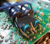
However, I tried to add 100uF across the zener and R (R7,D1 and R8,D2) for the OP-amp, since I believe the OP is starved of a proper low impedance power supply path.
That caused a lot of hum, so I never auditioned that mod properly. (Not sure why as the caps were across the small signal rails only.)
Instead I put the two 100uF over just the zeners (D1 and D2), like the smaller decoupling caps, and the result was truly jaw-dropping! (Try it!) I have only tried this with the rather demanding AD797, but wouldn't be surprised if it helps a lot even with the TL071.
RogerGustavsson said:
Hej Patrik!
I think the low pass filter formed by R12 and C6 can be detected. From tests made in Sweden years ago, a simple filter like this need to have a cut off frequency above 130kHz in order to be inaudible. At the other end of the spectrum, the cut off should be below 0.3Hz.
Roger
Hi Roger!
Probably, but I'm not mucking with the HP and LP filtering unless I'm 100% sure the internals will be able to follow the signal without TIM. I believe the 405 is designed so TIM won't happen as long as the signal confirms to the input filtering.
(Edit: I call it TIM, but I suppose it's slew rate limit induced distortion. Is it the same thing?)
Regards
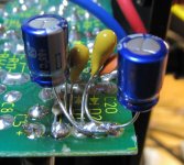
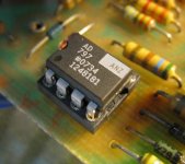
OP-amp bypass: 100pF (supposed to be 100nF, to be fixed), 4.7uF tantalium, and 100uF cap.
Edit: Apart from a jaw-dropping improvement in sound quality, the 100uF also lessened turn-off thumps (which were initially worsened by inserting the AD797).
Edit: Apart from a jaw-dropping improvement in sound quality, the 100uF also lessened turn-off thumps (which were initially worsened by inserting the AD797).
Attachments
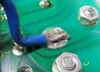
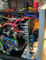
Power ground. Goes to speaker out neutral post. Replaces screw that sent power ground into chassis (via various screws and even thermal paste!). Knee is due to additional mod, I'll re-do the cabling later. Lot's of prototype type stuff for now!
Attachments
- Status
- This old topic is closed. If you want to reopen this topic, contact a moderator using the "Report Post" button.
- Home
- Amplifiers
- Solid State
- Kit building Quad 405 Clone