There was a crossover done by KEF for the Australian run of Concertos... or maybe also only Concerto Kit... the famous and elusive "Auskef Crossover". It looked much more like the CS7 version. CS7 and Cantata crossovers differ in their values for the mid filter. So what you suggest all needed to be tried. If you have a Cantata crossover, why not try it? The caps might be beyond their best years, though – and a recap again needs careful tuning and parts selection. So it becomes a bit circular. Re the place of the Zobel: I know, as addressed in the last post. The change of the crossover point is part of why it works, I'd be tempted to assume.
Yes there must be Auskef crossovers all over Australia without people knowing what they have. I'll have to take a closer look at the ones I have, although they do say DN12 on them. Unfortunately I have spare Concerto crossovers not Cantata but I might add your mods to them and see how they sound in a TL. Of course I'll test the caps first and see if any are still useable. Thanks for the information.
Hello Gentlemen, I’ve recently been researching various crossovers for the B139, B110, T27 3 ways. I have a set of custom ‘Bailey’ TLs loaded with a kit from Kef Concerto Constructor series circa ’79-80 imported from Wilmslow.
The Baileys cabinets are the revisited version having the triangulated internals form rather than the IMF style of channelling.
I haven’t used them in over thirty years
As tragic vintage collector/hoarder, I also have the Coles super tweeters and a pair of Falcon crossovers.
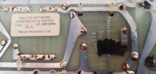
So my Falcons are 4 way Type 16R HP (PCB 5) but have no info or intended purpose. I’ve tried contacting FA but they seem to out of the office ATM and their archive info non-existent. I figured I could modify these Falcons using new caps and perhaps my existing DN12 components to make an updated 4 way using the excellent knowledge and insight here at DIY Audio. Any schematics or suggestions appreciated.
The Baileys cabinets are the revisited version having the triangulated internals form rather than the IMF style of channelling.
I haven’t used them in over thirty years
As tragic vintage collector/hoarder, I also have the Coles super tweeters and a pair of Falcon crossovers.
So my Falcons are 4 way Type 16R HP (PCB 5) but have no info or intended purpose. I’ve tried contacting FA but they seem to out of the office ATM and their archive info non-existent. I figured I could modify these Falcons using new caps and perhaps my existing DN12 components to make an updated 4 way using the excellent knowledge and insight here at DIY Audio. Any schematics or suggestions appreciated.
Attachments
Hi Gtegegg, this looks very interesting.
Would it be possible to post a photo which shows all the component numbers (shot from directly above)? And a full shot of the copper tracks of the underside? Falcon did not by chance provide a schematic with this (and you still have it)?
Would be helpful if this circuit could be tracked and published. Thank you!
Here you can find lots of information:
https://hifiloudspeakers.info/speakertalk/viewforum.php?f=6
https://hifiloudspeakers.info/Anatomy/Anatomy.html
https://hifiloudspeakers.info/speakertalk/viewforum.php?f=6
https://hifiloudspeakers.info/Anatomy/Anatomy.html
Hi, Eschenborn, I've spent quite a bit time on various threads for a schematic to no avail. Will trace out the circuit and post it here. I've started and now aware that there is a 5th way via 2.2uf tap off the HF. I wish I had researched for a schematic back when I bought these on eBay about 15 years ago. I just wanted to confirm that the HF was for the T27 and not for Celestions because I have a pair of HF1300 which I probably bought around the same time.
By the way, I liked your posts with respect to dialing in the B110 and revisiting the Kef DN12. I'm fairly sure that the Falcons are for the B139 and B110 as the Elcaps are 72uF in the LF and 60uf in the MF similar to many of the circuits I've been looking at so far.
Anyway, thank you for your reply here and your earlier posts re; the B110. Posting soon with Pics.
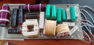
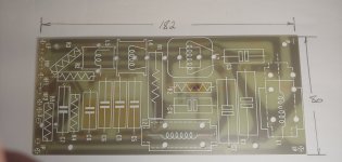
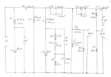
Hello Everyone, have sketched out the Falcon PCB-5 4/5 way crossover and stripped the components to show the screen print overlay and provide a better photo of the foil side. I am still interested in the original design purpose and suitability for original Kef B139 B110 based 3/4 ways.
Notes: Erratum- there are two R2 resistors. (Falcon Mfg fault)
L1 & L2 are ferrite cored, L3,L4, & L5 are air cored.
C1, C2, C3 and C4 are Falcon Elcaps (Black with the red sealed ends. C5 and C6 parallel pairs are "ERIE 250VDC Type M312.
All resistors are ceramic and guessing 5 watt excepting R1 which is much larger and probably 10 watt.
Also, there appears to be some over heating of R2 in the MF circuit as can be seen in the attached photos. Any comments appreciated.
Attachments

I looked at the circuit again with more time.
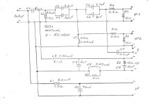
I think – if I got it right – there is a slight error in your schematics regarding the mid and tweeter circuits: L2 is in the input to both, it goes to ground after the 60uF series cap C2 and from there the tweeter circuits take their input, obviously after the first stage of mid filtering (unusual).
8.8mH is a huge value for L2. did you measure the inductors or did they have their values written on them? L3 and R1 in tank constellation to ground on the negative B110 terminal are also unusual. The B110 is wired here with the input to the positive terminal where in the Concerto it is wired to the negative one.
It is also a bit funky that they provided for paralleled caps in the tweeter circuit, why actually? these old Falcon universal PCBs are pretty all-round. I am in the process of abusing one (the Chorale high power PCB) in order to create new crossovers for a pair of KEF 103.2s which came with one crossover missing (and the tweeter wired directly to the input an... of course shot. who does such a thing?)... but still have to drill some new wholes for some parts.
Thanks again for taking all the components off, so much work you did, very very helpful. I hope the traces which came off the PCB can be repaired easily.
Hello All
Hi Eschenhorn, thanks for the reply. My schematic is correct since having the PCB stripped I was able to double check by confirming each component connection.
If U check the screen overlay at the very bottom of the pic, the + copper foil rail has only 2 outgoing holes for L1 and C2 forming the start of low and high pass filters. Also, I have not nominated the connection polarity of the midrange driver or indeed what driver the xover was for. I guess that is why I’m here asking you guys.
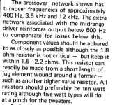
My best guess is that this crossover was something like the Webb TL using the Coles super tweeter and the 15 ohm damping resistors across each of the outputs is to match the 16 ohm output impedance of a valve amplifier.
As mentioned in my earlier post, the xover could also have been designed for a Celestion top end.
Oh, yes the Inductance measurements were with a cheap multimeter and so should be taken as ball park measurements. The meter was brand new out of the box.
Re: Lifted tracks, I have repaired much worse and will probably use it as daughter PCB to larger tag/termination board so I can use larger terminals and thicker gauge cable.
Do have a recommended replacement for the 72uF and 60uF elcaps? That is if I were to rebuild to this schematic? I am still curious why electrolytics, according to your listening tests perform better than the current batch of crossover film foil caps. Anyway, cheers.
Hi Eschenhorn, thanks for the reply. My schematic is correct since having the PCB stripped I was able to double check by confirming each component connection.
If U check the screen overlay at the very bottom of the pic, the + copper foil rail has only 2 outgoing holes for L1 and C2 forming the start of low and high pass filters. Also, I have not nominated the connection polarity of the midrange driver or indeed what driver the xover was for. I guess that is why I’m here asking you guys.
My best guess is that this crossover was something like the Webb TL using the Coles super tweeter and the 15 ohm damping resistors across each of the outputs is to match the 16 ohm output impedance of a valve amplifier.
As mentioned in my earlier post, the xover could also have been designed for a Celestion top end.
Oh, yes the Inductance measurements were with a cheap multimeter and so should be taken as ball park measurements. The meter was brand new out of the box.
Re: Lifted tracks, I have repaired much worse and will probably use it as daughter PCB to larger tag/termination board so I can use larger terminals and thicker gauge cable.
Do have a recommended replacement for the 72uF and 60uF elcaps? That is if I were to rebuild to this schematic? I am still curious why electrolytics, according to your listening tests perform better than the current batch of crossover film foil caps. Anyway, cheers.
The two kinds tend to have different parasitic resistance values (all things have some resistance, usually small.. even if it's not intended).I am still curious why electrolytics, according to your listening tests perform better than the current batch of crossover film foil caps.
This can change the balance, as if regular resistance was used. It also accounts for differences people may hear, so whenever you read a review, see whether it has been accounted for before assuming there are other differences.
Hi AllenB, the original red/black Alcaps have drifted up i.e 72uF is reading 124uF and the 60uF is reading 84uF (Fluke 27). These values are a fair bit of tolerance and since I'm really pursuing a modest restoration of Kef B139 B110 T27 Bailey TL that has been stored since 1985 in a corner bedroom. Never played a tune since then. I'm sure U remember 'Dire Straits', 'Australian Crawl' that era. Anyways I'm revisiting them for nostalgic reasons and then moving them on.
So, my effort is here is to research which crossover is best to rebuild, that is either Falcon PCB-5 or Kef DN12.
In the end they will not compete with my JBL 250Ti or Duntechs, no matter what caps I use. To me, in this situation, the cost of Mcaps or Elcaps electros are bit overhyped and overpriced (for me anyways) but I want them to go a good home. So, a half decent recap using inexpensive NP electros or other hand, the film/foil caps have longevity.
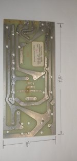
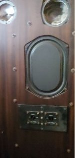
The front and back panels are 25mm particle board with front and back panels able to be removed to load the transmission line with suitable fill. I never did get that anywhere near right. So plenty to do besides the crossover. The cabinets were custom made by Southport HiFi here on the Gold Coast. I did the final fitting out and sealing of panels. These panels fixings are severely over engineered which what I was like back in the day... Here is a pic, sorry about the quality, but its hard to get to ATM.
So, my effort is here is to research which crossover is best to rebuild, that is either Falcon PCB-5 or Kef DN12.
In the end they will not compete with my JBL 250Ti or Duntechs, no matter what caps I use. To me, in this situation, the cost of Mcaps or Elcaps electros are bit overhyped and overpriced (for me anyways) but I want them to go a good home. So, a half decent recap using inexpensive NP electros or other hand, the film/foil caps have longevity.
The front and back panels are 25mm particle board with front and back panels able to be removed to load the transmission line with suitable fill. I never did get that anywhere near right. So plenty to do besides the crossover. The cabinets were custom made by Southport HiFi here on the Gold Coast. I did the final fitting out and sealing of panels. These panels fixings are severely over engineered which what I was like back in the day... Here is a pic, sorry about the quality, but its hard to get to ATM.
Attachments
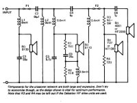
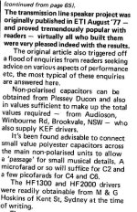
Hello metako, I noticed in your earlier post you said you have been using the ETI/Atkinson/Crabbe/Frisby circuit for your TL. Can you confirm that the circuit I've attached is what you have in your TL? I am curious since it has the HF1300 as an alternate to the T27. The Falcon PCB-5 circuit I've posted here has a lot of similarities.
Attachments
That's also a very interesting crossover. And pretty similar to yours in how it treats LF and MF. it could be build on the Falcon No 5 board ")
You did a fantastic job @Gtegegg in tracing out the crossover. I am still seeing that the L2 inductor to ground (as typical) is also part of the MF filter like in the ETI crossover you post above. In your drawing it is only part of the tweeter filter. see my little arrows below:

You did a fantastic job @Gtegegg in tracing out the crossover. I am still seeing that the L2 inductor to ground (as typical) is also part of the MF filter like in the ETI crossover you post above. In your drawing it is only part of the tweeter filter. see my little arrows below:
Jaycar do these.using inexpensive NP electros
Hi AllenB, Wagner's have better range but I have since checked back again with Falcon Acoustic on-line and it seems they do matched pairs and can screen for tighter tolerance. Been thinking that I probably need a Capacitor kit for some JR149s, perhaps I should piggy-back the 72uf and 60uf caps on a single order to help mitigate shipping costs. Somebody on this forum, if remember correctly, said that FA shipping is quite expensive.
Hi Eschenhorn, I'm missing your point, the topology looks the same to me. Perhaps I should redraw it in the ETI style. By the way, the ETI crossover (1977 article) was based on the Frisbee article from 1974 using the T15. I have attached the schematic here.
Also, I have the design notes from the 1977 article concerning the capacitors used. Paper in Oil caps from Fluorescent lights. I also note that it recommended to bypass the caps with smaller values like JBL do to counteract against the parasitic inductance of the cap.and letting the sparkly bit thru to the tweets. (as I understand it)
Attachments
seen
Hi Gtegegg, sorry for the late reply but I have other non-hifi things demanding my time atm. Yes that's the crossover I have. The treble part seems good especially with poly caps, the mids seem totally out of balance to my ears, and the bass is too dry and lacking. 100uF instead of 55uF with the B139 (which I saw used in an IMF crossover) sounds alot better to me, warmer and more abundant and go some way to put the mids into better balance. If you could put your Falcon crossover into ETI style it would be very helpful to see what they're doing there. I can't help but feel that the "bafle step" section on the mids using the 0.5mH + 1.8ohm is doing something odd, as it was originally inserted for Atkinson's super-wide mid baffles for use with horn bass drivers. Its supposed to add 1dB below 600Hz but I wonder what its really doing.Hello metako, I noticed in your earlier post you said you have been using the ETI/Atkinson/Crabbe/Frisby circuit for your TL. Can you confirm that the circuit I've attached is what you have in your TL? I am curious since it has the HF1300 as an alternate to the T27. The Falcon PCB-5 circuit I've posted here has a lot of similarities.
Last edited:
Hi Metako and Eschenhorn and all U lurkers, I have redrawn the Falcon crossover in the ETI/Frisby style and the treatment is very similar except the 6-8 ohm in parallel with B139 in 1974 circuit. I have ordered some capacitors (el-cheapos) from China and will get back here in couple of months.
I have for the most part, answered my own questions regarding the Falcon PCB-5 Type 16 R HP but was hoping for some of the original designer's intent and application notes. i.e What was C7 and No. 3 output for.
Note: the labels on schematic in post #69 HF1 and HF2 are incorrect and should be reversed.
Attachments
- Home
- Loudspeakers
- Multi-Way
- KEF Concerto improved DN12 crossover with full aB circuit