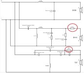
I would say the most sensitive pieces in this crossover are the 10uF capacitor in series with the 10 ohms resistor parallel to the midrange speaker, the 3.3 uF capacitor at the input of the tweeter filter network, and possibly the inductor coil in the woofer network. Substituting the woofer inductor with one with a larger wire diameter and less in a resistance might give good results, although with this crossover bass is there in spades. The 10uF capacitor might be substituted by a plastic film type, but then the 10 ohms series resistance might be too low and should be raised to 12. But I did not empirically check this.
anyway the crossover as I built it did not leave anything to desire, and I cross compared with 105 rederence speakers. I still prefer the Concerto with his crossover to the Cantata with the serviced factory crossover.
anyway the crossover as I built it did not leave anything to desire, and I cross compared with 105 rederence speakers. I still prefer the Concerto with his crossover to the Cantata with the serviced factory crossover.
Hello M. Eschenborn (and the community)
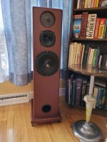
I have built some time ago some "Pseudo Concerto" (see attached picture) using Kef's DN-12/T27/B110 but for the woofer, I used some Pearless 8" "Extra Long Stroke" woofer (P/N 830491) which I beleive have a lower SPL than the Kef 139. I drive them using fully refurbished QUAD 405-2/34 Amp/Pre-Amp units with sources from either a Thorens turntable/Naim CD/Rotel FM/Topping streamer.
I always found the bass a bit weak but "lived" with them "as-is" since 2006 until last year when I decided to "finally complete these spekers" to the best they could sound. First, I spent time getting the bass I was missing by optimizing my enclosure size (volume was too big) and then changed the old electolytic capacitors of the DN-12 with Falcon's Alcap of 100V & 5% for the 7/30/80 uF capacitors and 100V & 5% low-loss Alcap's for the 5 uF capacitors (used for the tweeter section).
After these modification, the Tweeter & Midrange section were much more detailed with better dispersion but both seemed now "too loud" for the woofer section. I decided the dial them down using simple L-Pads and ended-up with -3.0 dB for the T27 and -5.5 dB for the B110 which results is a quite nicely balanced warm & detailed sound but I don't like the fact that I am "loosing power" into L-Pads. I then changed the electrolytic capacitors for the tweeter and midrange sections for polypropylene film type (i.e. Solen's "Fast Cap") with an exact value of 30 uF for the B110 and a pair of 5.1 uF for the tweeter and the result is indeed a reduction in "apparent loudness" of the midrange (so I could probably reduce the L-Pad) but the "sound color" is different and I am not sure I like it better. After reading related posts, the user Marintz has sucessfully used a polypropylene capacitor for the midrange so maybe this change is "good" so maybe this "color change" may also be due to the 5.1 uF polypropylene film capacitors used for the tweeter filter so maybe I have to revert back to the electrolytics as I beleive you stated that you observe that changes done in the T27 filter percolates down on the other ranges so the tweeter section seems "tricky". So here are my 5 questions to you (or others):
- Is using a polypropylene film type of 30 uF on the orignal DN-12 a "good upgrade" or since its ESR is lower, it is not a good idea if the rest of the X-Over is unchanged.
- For the tweeter section, same question as above for the polypropylene film type capacitor.
- I read that the B110 are notorious for having a "forward color" so I am wondering if just adding an impedence equalizing circuit (i.e. 10 Ohm /10 uF parallel circuit) could result in a "less loud" midrange which may allow a reduction of the L-Pads value or this approach is not ideal.
- In your DN-12 upgrade, do I understand right that you are changing the tweeter's iron core inductor of .25 mH to an air core type of .30 mH but re-using the original induction is OK. Please confirm.
- If I implement your DN-12 upgrade, could I adjust for my lower SPL woofer by only changing the final "amp side" resistor or 2.2 Ohm of the B110 and 3 Ohm of the tweeter to balance things out or this won't work. Please advise.
Attachments
Hi @Marctheroad , thank you. Nice speakers!
Interesting story. Here some general comments and then the answers to your questions in numerical order:
– the Concerto, with the adapted crossover, is a very competent speaker: big, bold, detailed, warm, great imaging.
– the DN12 is a bad crossover, particularly in terms of how the B110 is handled, even with fresh capacitors, better to modify it (see below)
– it is a challenge to integrate a different driver into a given driver line-up and the connected thought of how to cross over the drivers, handle the sensitivities. if your woofer is not loud enough, and even has a lower sensitivity than the B139, then the other drivers need to be "padded down" as you did. you don't like to "burn" SPL, but it is the only way to get the balance right. In a way the DN12 is the wrong crossover for your speaker because you have a different woofer.
– you constructed a bass reflex design. is the -3dB point the same as for the Concerto? in other words, did you get the bass reflex right? did you calculate and simulate (and measure) it?
– if you already build a new enclosure, why not use the original B139? even new, with higher excursion, from Falcon Acoustic?
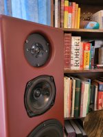
– I see that your tweeters are recessed in a sort of horn arrangement. Their SPL will be probably too loud because of this anyway. as the rim is pretty sharp, there might also be some reflections leading to some peak in the tweeter spectrum. could you put a thick gasket under the tweeters and raise them from their "holes"?
– if you use plastic caps instead of electrolytics, the sound level and the sound balance of the respective driver will change – in what way needs to be "heard". if you want to use a (very big and bulky) 30uF film cap in series with the B110, you could pad it down a bit more with a higher series resistor. I don't use wordings like "good sound colour" etc, I think that either a driver/speaker is flat, i.e. linear, and will sound right, or, if not flat and with dips and peaks, it sounds wrong (although that might seem interesting for a while/some listeners)
– the B110 is nice, but has some peaks that either need to be filtered (like in the R101 or LS3/5A) or rolled of (like in the R105) or be neutralized by lowering the overall mid volume (like I did in my crossover version). It would be interesting to add a notch filter to the B110 circuit. But I never tried.
now your questions:
1. if padded down with series resistor might be ok, but it does not have a lot of effect and it is a bulky hack. I would not do it.
2. here the input capacitor can be a film --> adapt resistance
3. forward colour is one of those descriptions... the driver actually has a +5dB peak in the 800-1000Hz region. adding a Zobel is of great help, I did it in "my crossover"
4. yes, the inductor is changed, as the whole tweeter network with the addition of the aB circuit. the new inductor value is mandatory. does not need to be aircore
5. you can raise the 2.2.Ohm. The 3 Ohm resistor in the tweeter circuit has a different function. If you want to lower the tweeter network, put a resistor at the input. but I did not find that it is needed.
please report your next steps, I am curious how it turns out.
Interesting story. Here some general comments and then the answers to your questions in numerical order:
– the Concerto, with the adapted crossover, is a very competent speaker: big, bold, detailed, warm, great imaging.
– the DN12 is a bad crossover, particularly in terms of how the B110 is handled, even with fresh capacitors, better to modify it (see below)
– it is a challenge to integrate a different driver into a given driver line-up and the connected thought of how to cross over the drivers, handle the sensitivities. if your woofer is not loud enough, and even has a lower sensitivity than the B139, then the other drivers need to be "padded down" as you did. you don't like to "burn" SPL, but it is the only way to get the balance right. In a way the DN12 is the wrong crossover for your speaker because you have a different woofer.
– you constructed a bass reflex design. is the -3dB point the same as for the Concerto? in other words, did you get the bass reflex right? did you calculate and simulate (and measure) it?
– if you already build a new enclosure, why not use the original B139? even new, with higher excursion, from Falcon Acoustic?
– I see that your tweeters are recessed in a sort of horn arrangement. Their SPL will be probably too loud because of this anyway. as the rim is pretty sharp, there might also be some reflections leading to some peak in the tweeter spectrum. could you put a thick gasket under the tweeters and raise them from their "holes"?
– if you use plastic caps instead of electrolytics, the sound level and the sound balance of the respective driver will change – in what way needs to be "heard". if you want to use a (very big and bulky) 30uF film cap in series with the B110, you could pad it down a bit more with a higher series resistor. I don't use wordings like "good sound colour" etc, I think that either a driver/speaker is flat, i.e. linear, and will sound right, or, if not flat and with dips and peaks, it sounds wrong (although that might seem interesting for a while/some listeners)
– the B110 is nice, but has some peaks that either need to be filtered (like in the R101 or LS3/5A) or rolled of (like in the R105) or be neutralized by lowering the overall mid volume (like I did in my crossover version). It would be interesting to add a notch filter to the B110 circuit. But I never tried.
now your questions:
1. if padded down with series resistor might be ok, but it does not have a lot of effect and it is a bulky hack. I would not do it.
2. here the input capacitor can be a film --> adapt resistance
3. forward colour is one of those descriptions... the driver actually has a +5dB peak in the 800-1000Hz region. adding a Zobel is of great help, I did it in "my crossover"
4. yes, the inductor is changed, as the whole tweeter network with the addition of the aB circuit. the new inductor value is mandatory. does not need to be aircore
5. you can raise the 2.2.Ohm. The 3 Ohm resistor in the tweeter circuit has a different function. If you want to lower the tweeter network, put a resistor at the input. but I did not find that it is needed.
please report your next steps, I am curious how it turns out.
Last edited:
Hello M. Eschenborn
Let me first thank-you very much for your reply and see below answers to your questions and follow-on replies.
I built these speakers 20 years ago and with the aging Elcap capacitors of the DN-12, I guess I did not hear the progressive loss of details and was "fudging" the inherent weak base of these enclosures by adding a +3 dB "tilt" on the QUAD 34 pre-amp. When I renewed the capacitors of the DN-12, details suddently "stuck my face" and the inherent bass weakness was too apparent to do nothing. At the time I did these speakers, the design recommendatoin I got from the seller was to have an internal box volume of 50 litres for a tuned frequency of 29 Hz using a 3"x12" port (i.e. this Peerless woofer is a High Definition series with an extra-long stroke). As for the speaker construction, all the walls are made of 19 mm thick high density fiber board with an extra thickness on the front baffle. The B110 has its separate chamber of 4 litres (Kef spec when used as a midrange) and also serves as braces for the sidewalls. All innner walls, including the separate MF enclosure, are lined up with accoustic foam. The crossover is located inside the box at the bottom under the port tube.
Based on the woofer's Vas (85.36l), Fs (29.3 Hz) and Qts (0.307) and using "Keele's" calculator equations for vented box, the box volume Vb should be closer to 43,2 l for a tuned frequency of 39.8 Hz and a -3db point at 35.6 Hz so it looks like my enclosure is too big with the port not optimal either. I started to fill the bottom area using some hard isolation styrofoam, reshaped in inner baffle wall around the woofer (38 mm thickness baffle with a top mounted woofer lead results in airflow restriction around its inner peripehry), cut the port tube and added an elbow since the original installation lead to less than 1" at the back of the port tube. With these changes, there is a good improvement with A/B testings but I know I am not there yet. I am not sure if I will be able to attain a "reasomably good alignment" with my ear only as I found that a dB meter is not really usefull as the sound it is more "felt" than heard at these lower frequencies. Any "trick of the trade" on this matter would be usefull") Only instrument I have is a dB meter, a frequency generator and a 1/3 octave pink noise vinyl disk.
Only instrument I have is a dB meter, a frequency generator and a 1/3 octave pink noise vinyl disk.
I was initally planning to buy new B139 from Falcon but based on the price tag, and knowing that the current enclosure could be improved, I decided to give a try with my existing woofers.
The tweeter (new Falcon units) are recessed by 19 mm since 20 years ago, I was told that it is better to "vertically align" the driver's inner domes to ensure that thier reproduced sound reach our ears at the same time. Based on your comment, although I did implemented a rounded corner (see picture), your may be right that the sound can bounce-off the sidewalls and indeed, based on "my standard dB meter test" which I do, I do see a peak around 7,500 Hz so for sure, I will bring one of them flush and do an AB test to compare.
On the subject of the capacitors, as stated above, I already changed the capacitors of one of the crossovers on the HF and MF circuits with high quality plastic caps but what I heard was not convincing. Bottom line, are plastic cap, apart from thier longer life, really a must in HiFi or good quality electrolytics can result in an "as good" sound when the crossover is correctly designed. I see capacitors with crazy pricetag so would guess that it must bring some audible benefits as being claimed.
My next steps are then:
Let me first thank-you very much for your reply and see below answers to your questions and follow-on replies.
I built these speakers 20 years ago and with the aging Elcap capacitors of the DN-12, I guess I did not hear the progressive loss of details and was "fudging" the inherent weak base of these enclosures by adding a +3 dB "tilt" on the QUAD 34 pre-amp. When I renewed the capacitors of the DN-12, details suddently "stuck my face" and the inherent bass weakness was too apparent to do nothing. At the time I did these speakers, the design recommendatoin I got from the seller was to have an internal box volume of 50 litres for a tuned frequency of 29 Hz using a 3"x12" port (i.e. this Peerless woofer is a High Definition series with an extra-long stroke). As for the speaker construction, all the walls are made of 19 mm thick high density fiber board with an extra thickness on the front baffle. The B110 has its separate chamber of 4 litres (Kef spec when used as a midrange) and also serves as braces for the sidewalls. All innner walls, including the separate MF enclosure, are lined up with accoustic foam. The crossover is located inside the box at the bottom under the port tube.
Based on the woofer's Vas (85.36l), Fs (29.3 Hz) and Qts (0.307) and using "Keele's" calculator equations for vented box, the box volume Vb should be closer to 43,2 l for a tuned frequency of 39.8 Hz and a -3db point at 35.6 Hz so it looks like my enclosure is too big with the port not optimal either. I started to fill the bottom area using some hard isolation styrofoam, reshaped in inner baffle wall around the woofer (38 mm thickness baffle with a top mounted woofer lead results in airflow restriction around its inner peripehry), cut the port tube and added an elbow since the original installation lead to less than 1" at the back of the port tube. With these changes, there is a good improvement with A/B testings but I know I am not there yet. I am not sure if I will be able to attain a "reasomably good alignment" with my ear only as I found that a dB meter is not really usefull as the sound it is more "felt" than heard at these lower frequencies. Any "trick of the trade" on this matter would be usefull
Only instrument I have is a dB meter, a frequency generator and a 1/3 octave pink noise vinyl disk.I was initally planning to buy new B139 from Falcon but based on the price tag, and knowing that the current enclosure could be improved, I decided to give a try with my existing woofers.
The tweeter (new Falcon units) are recessed by 19 mm since 20 years ago, I was told that it is better to "vertically align" the driver's inner domes to ensure that thier reproduced sound reach our ears at the same time. Based on your comment, although I did implemented a rounded corner (see picture), your may be right that the sound can bounce-off the sidewalls and indeed, based on "my standard dB meter test" which I do, I do see a peak around 7,500 Hz so for sure, I will bring one of them flush and do an AB test to compare.
On the subject of the capacitors, as stated above, I already changed the capacitors of one of the crossovers on the HF and MF circuits with high quality plastic caps but what I heard was not convincing. Bottom line, are plastic cap, apart from thier longer life, really a must in HiFi or good quality electrolytics can result in an "as good" sound when the crossover is correctly designed. I see capacitors with crazy pricetag so would guess that it must bring some audible benefits as being claimed.
My next steps are then:
- Switch over the crossovers to confirm that the "color change" in the sound of the plastic cap crossover is not related to driver discrepancies and continue the testing in order to decide "which color" I like best.
- Add a spacer to the tweeter such as to bring its surface at the same depth as the B110 as it seems to be the case based on pictures I saw of the Concerto's.
- Continue to add solid filler inside the box in order to reduce its volume and adjust the port as needed.
- Order the parts I need to implement your crossover design on one side. I will review your part's list tomorrow and verify what I can easily get and for sure, I would like to reuse the new ALCAP electrolytics I just purchased if possible.
Attachments
Good Morning,
thank you for the step-by-step description. Some remarks:
– the problem with plastic caps is that they have different electrical specs than the bipolar electrolytics originally used. so if you insert them, your crossover will not function as intended by the designers. plastic caps have great qualities, but these do not help if their specs do not match and the response is not flat. if you simply swap them with old electrolytics, chances are that the response becomes subjectively bright or strident. So what happened when you put in films instead of the old elcaps was that your already wrong tonal balance shifted to "even more wrong". so plastic caps might be great if you design your circuit from scratch, but probably will ruin things if it is a vintage circuit.
– you talk about your current enclosure not being "optimal". again it is more a question of maths, either you have the right parameters in terms of giving you the intended frequency extension and flat-as-possible response, or you don't, and then it will sound wrong in one way ore another. so what you call a "reasonably good alignment" will still sound wrong if it is not the ideal alignment that you can achieve with the given specs (of the woofer and the case).
– the current bass circuit of the DN12 you are using might not be optimal for the SEAS driver. it's possible that the SEAS driver is separated to high or too low. using a different driver with a given circuit is always problematic and requires a lot of trial and error. one more reason to use the original B139.
– the wire of the bass coil in the DN12 is relatively thin, if you use another coil (I-core with thick wire, or a fancy flat-wire indictor with very low R, your bass performance might rise. but again, if the crossover does not do the right things, this might make stuff even worse.
– you find good and cheap used original B139s. It's a great woofer, and all the parameters are known.
– AB-comparisons with stereo speakers when one is restored/ modified and the other not are misleading. I always change both speakers in a stereo pair and listen to them in stereo. you can trust the crossover design I posted, I tested it over weeks, it sounds great – in the original concerto setup, with B139 and the box volume of the concerto
– if the inner enclosure for the B110 is too close to the back wall and there is only a narrow air passage between the upper volume behind the tweeter and the lower volume behind the woofer, you might have created a resonator --> even more distorting your intended results, as producing its own acoustical effects
– there is no evil with dialing in +3dB or even more of bass equalization through your preamp. having a tone control is very helpful (you don't need to buy expensive cables which change the response of your system
– don't try to reuse the already bought caps if they don't have the right values it will sound wrong. don't try the aB circuit with the old inductor. it will sound wrong. the aB circuit KEF added to the T27 circuit btw has ripple effects far down into the mids and so makes the mids more linear, which is very audible.
– again: you reported good results with some series resistance in the tweeter and mid circuits, to bring their level closer to that of the woofer. I'd suggest that you get the reflex alignment right and "pad down" the other drivers, and voilà. you can do this by using "my" crossover and adding series resistance at the inputs of the mid and high circuits.
– if you want to try a quick and dirty improvement, do this (on both speakers): re-install the series resistances to the mid and tweeter circuits, add the zobel network (10R and 10uF) across the B110, add the 1R resistance in series with the 6.8uF cap in the mid circuit. if the 6.8uF is now plastic, instead add a 2R or 3R resistor in series with it (5 or 10 Watts).
thank you for the step-by-step description. Some remarks:
– the problem with plastic caps is that they have different electrical specs than the bipolar electrolytics originally used. so if you insert them, your crossover will not function as intended by the designers. plastic caps have great qualities, but these do not help if their specs do not match and the response is not flat. if you simply swap them with old electrolytics, chances are that the response becomes subjectively bright or strident. So what happened when you put in films instead of the old elcaps was that your already wrong tonal balance shifted to "even more wrong". so plastic caps might be great if you design your circuit from scratch, but probably will ruin things if it is a vintage circuit.
– you talk about your current enclosure not being "optimal". again it is more a question of maths, either you have the right parameters in terms of giving you the intended frequency extension and flat-as-possible response, or you don't, and then it will sound wrong in one way ore another. so what you call a "reasonably good alignment" will still sound wrong if it is not the ideal alignment that you can achieve with the given specs (of the woofer and the case).
– the current bass circuit of the DN12 you are using might not be optimal for the SEAS driver. it's possible that the SEAS driver is separated to high or too low. using a different driver with a given circuit is always problematic and requires a lot of trial and error. one more reason to use the original B139.
– the wire of the bass coil in the DN12 is relatively thin, if you use another coil (I-core with thick wire, or a fancy flat-wire indictor with very low R, your bass performance might rise. but again, if the crossover does not do the right things, this might make stuff even worse.
– you find good and cheap used original B139s. It's a great woofer, and all the parameters are known.
– AB-comparisons with stereo speakers when one is restored/ modified and the other not are misleading. I always change both speakers in a stereo pair and listen to them in stereo. you can trust the crossover design I posted, I tested it over weeks, it sounds great – in the original concerto setup, with B139 and the box volume of the concerto
– if the inner enclosure for the B110 is too close to the back wall and there is only a narrow air passage between the upper volume behind the tweeter and the lower volume behind the woofer, you might have created a resonator --> even more distorting your intended results, as producing its own acoustical effects
– there is no evil with dialing in +3dB or even more of bass equalization through your preamp. having a tone control is very helpful (you don't need to buy expensive cables which change the response of your system
– don't try to reuse the already bought caps if they don't have the right values
it will sound wrong. don't try the aB circuit with the old inductor. it will sound wrong. the aB circuit KEF added to the T27 circuit btw has ripple effects far down into the mids and so makes the mids more linear, which is very audible.– again: you reported good results with some series resistance in the tweeter and mid circuits, to bring their level closer to that of the woofer. I'd suggest that you get the reflex alignment right and "pad down" the other drivers, and voilà. you can do this by using "my" crossover and adding series resistance at the inputs of the mid and high circuits.
– if you want to try a quick and dirty improvement, do this (on both speakers): re-install the series resistances to the mid and tweeter circuits, add the zobel network (10R and 10uF) across the B110, add the 1R resistance in series with the 6.8uF cap in the mid circuit. if the 6.8uF is now plastic, instead add a 2R or 3R resistor in series with it (5 or 10 Watts).
Good evening M. Eschenborn
Again, tanks so much for taking the time to reply me. I am new to this site and did "save draft", left the site, came back and saw that I lost all my previous writings which explains my deplay in replying.
So for plastic caps, thanks for your explanation that since thier electrical characteristics are different, just swapping original electrolytics to plastics caps cannot "improve things" and I just observed this after swapping my crossover in which one had plastic caps for the HF & HF circuit and the impact was exactly as you predicted ... too bright & strident so for sure, less "musical". So my crossovers are now back with the new ALCAP electrolytics on both sides. Just amazing how much information is on the internet which states that if your just change the capacitors from electrolytics to plastic, "magic" will occur! Electrically speaking, I guess the most significant impact is on the ESR which is extremely low on plastic caps compared to electrolytics but I guess there are other important factors which, at the end, impact what you reference as the "balance" of the crossover which is a new term to me.
Your comment on the possibility that the low pass on the DN-12 might be cutting the frequency of my Peerless (i.e. not SEAS) woofer higher or lower than the 400 Hz of the DN-12 is probably correct as I know the DC resistance is a bit lower (5.86 V Vs 6.6 V for the B139) and it's inductance a bit higher (0.63 hH Vs 0.56 for the B139) so what I plan to do, as you suggested, is to replace the original DN-12 LF inductor with a new air core inductor of higher guage (16 should be sufficient, right?) and match the current 80 uF capacitor to address the woofer specification differences to increase the output level of the woofer. I have to learn how to calculate the required inductor/capacitor to ensure proper cut-off operation and hope that this change will minimally affect the "the final balance" of the crossover hence is not a "too risky" approach. The problem with readily using B139s (as you suggest) is that I don't have enough volume to ensure optimal output having only 54 litres net (without counting 1" accoustic foam lining all the walls nor the space taken by the crossover). Based on the KEF spec, a net volume of 30-40 litres is required for a closed box and 60-140 litres for a reflex enclosure which is why I want to first try to make my Peerless work.
To answer your question about the space left behind the MF enclosure, the area is more than 7 times bigger (49 in2) than the 3" port I use (7 in2) so I beleive that there is no risk of a resonator effect and for the optimization of the bass extension, I will have to seek further what kind of minimal equipment I need to help me to get to an "exact" alignment". Due to the spec of my woofer, it looks like a SBB4 alignment could be ideal and this is what I will be after but this will be addresses under a separate post.
For the HF and MF section, I plan to implement your crossover modifications but I was not able to find a site which has all the components you specified so do you have a suggestion for me of a site which I can buy the same quality with the exact specifications you mentionned? I guess you don't sell kits?.
I am currently making solid wood spacers in order to raise the tweeters out of their holes by about 15 mm and hope to hear better dispersion with a reduced overall level allowing me the reduce the L-Pads. I was able to measure +20 dB transients peaks near the rounded edge of the "holes" into which the tweeters are mounted so I am optimistic that this change will work for the better!
Thanks again!
Again, tanks so much for taking the time to reply me. I am new to this site and did "save draft", left the site, came back and saw that I lost all my previous writings which explains my deplay in replying.
So for plastic caps, thanks for your explanation that since thier electrical characteristics are different, just swapping original electrolytics to plastics caps cannot "improve things" and I just observed this after swapping my crossover in which one had plastic caps for the HF & HF circuit and the impact was exactly as you predicted ... too bright & strident so for sure, less "musical". So my crossovers are now back with the new ALCAP electrolytics on both sides. Just amazing how much information is on the internet which states that if your just change the capacitors from electrolytics to plastic, "magic" will occur! Electrically speaking, I guess the most significant impact is on the ESR which is extremely low on plastic caps compared to electrolytics but I guess there are other important factors which, at the end, impact what you reference as the "balance" of the crossover which is a new term to me.
Your comment on the possibility that the low pass on the DN-12 might be cutting the frequency of my Peerless (i.e. not SEAS) woofer higher or lower than the 400 Hz of the DN-12 is probably correct as I know the DC resistance is a bit lower (5.86 V Vs 6.6 V for the B139) and it's inductance a bit higher (0.63 hH Vs 0.56 for the B139) so what I plan to do, as you suggested, is to replace the original DN-12 LF inductor with a new air core inductor of higher guage (16 should be sufficient, right?) and match the current 80 uF capacitor to address the woofer specification differences to increase the output level of the woofer. I have to learn how to calculate the required inductor/capacitor to ensure proper cut-off operation and hope that this change will minimally affect the "the final balance" of the crossover hence is not a "too risky" approach. The problem with readily using B139s (as you suggest) is that I don't have enough volume to ensure optimal output having only 54 litres net (without counting 1" accoustic foam lining all the walls nor the space taken by the crossover). Based on the KEF spec, a net volume of 30-40 litres is required for a closed box and 60-140 litres for a reflex enclosure which is why I want to first try to make my Peerless work.
To answer your question about the space left behind the MF enclosure, the area is more than 7 times bigger (49 in2) than the 3" port I use (7 in2) so I beleive that there is no risk of a resonator effect and for the optimization of the bass extension, I will have to seek further what kind of minimal equipment I need to help me to get to an "exact" alignment". Due to the spec of my woofer, it looks like a SBB4 alignment could be ideal and this is what I will be after but this will be addresses under a separate post.
For the HF and MF section, I plan to implement your crossover modifications but I was not able to find a site which has all the components you specified so do you have a suggestion for me of a site which I can buy the same quality with the exact specifications you mentionned? I guess you don't sell kits?
.I am currently making solid wood spacers in order to raise the tweeters out of their holes by about 15 mm and hope to hear better dispersion with a reduced overall level allowing me the reduce the L-Pads. I was able to measure +20 dB transients peaks near the rounded edge of the "holes" into which the tweeters are mounted so I am optimistic that this change will work for the better!
Thanks again!
Hi @Marctheroad , sounds great.
Sorry that you lost your draft, highly frustrating! been there too. no worries though.
I'd use a big I-core inductor, it's cheaper and has low resistance. you can experiment with some capacitor values (56, 68, 82, 100 uF). eventually a small resistor in series with it stabilises things here as well.
if you have the thiele-small parameters for your Peerless bass (they should be findable) you can easily calculate the enclosure data (online calculator).
Actually I did some quick calculation and it shows that your enclosure is to big for a flat response, you lose 3dB between 250Hz and 40Hz, after which the low frequency cutoff is steep. But hey, it goes down to 40Hz which is nice, and the dip can be remedied by dialing in +2 on the bass knob as you actually did.
Good luck, keep us posted in terms of the tweeter. I still think physically sorting the tweeter, adding a Zobel across the B110 and padding the high and mid network down somewhat will solve your problems. or use my crossover and pad them down a bit more. it will turn out nicely.
Sorry that you lost your draft, highly frustrating! been there too. no worries though.
I'd use a big I-core inductor, it's cheaper and has low resistance. you can experiment with some capacitor values (56, 68, 82, 100 uF). eventually a small resistor in series with it stabilises things here as well.
if you have the thiele-small parameters for your Peerless bass (they should be findable) you can easily calculate the enclosure data (online calculator).
Actually I did some quick calculation and it shows that your enclosure is to big for a flat response, you lose 3dB between 250Hz and 40Hz, after which the low frequency cutoff is steep. But hey, it goes down to 40Hz which is nice, and the dip can be remedied by dialing in +2 on the bass knob
as you actually did.Good luck, keep us posted in terms of the tweeter. I still think physically sorting the tweeter, adding a Zobel across the B110 and padding the high and mid network down somewhat will solve your problems. or use my crossover and pad them down a bit more. it will turn out nicely.
I am just thinking that a great classic KEF driver for bass reflex enclosures is the venerable B200 SP1014. While KEF deployed different B200 versions with larger magnets and greater excursions for their bass reflex designs (104, Calinda, Cadenza), Tangent used the SP1014 in its TM-1 and -2, and these are fantastic sounding speakers. In those configurations the B200 SP1014 goes very low. And it would match the other KEF drivers in your system. It might fit into the existing hole. And it is cheap on the used market.
Hello M. Eschenborn
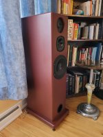
See below my new tweeter installation. The sound is less directional, as expected, but did not really allow me to drop my L-Pad which I kept at -3 dB. But for the B110, the impedence equalizer did magic resulting in a much fuller sound with a definite drop in certain "annoying" frequencies and at the end, I only added a 2.2 Ohm resistance added after the IE (exactly per your schematic of your new X-Over) hence I am very please with this.
As for the enclosure, the bass is much more present and I don't anymore have add + 3dB on my pre-amplifier so again, I am very satisfied. In fact, my final enclosure volume is 42.2 litres which is very close to the calculated optimal box volume of 42.69 litres based on my woofer parameters and the orignal Theile/Small equations. Note that I also had to reduce my 3" dia. port lenght from 12" to 9" which "should have resulted" in a box tuning frequency of 35 Hz but I don't have instrumentations to measure this but for sure, it sounds much tighter and better than before!
But overall, althoug my work (with your gratefull support) allowed me to significantly improve the overall sound of my enclosures, I am tempted to beleive that it is not "the best" that these drivers can deliver so I am seriously considering of making a set of new crossovers based on your design to benefit from the "aB circuit" which you state as having ripple effects down into the mids which makes the mids more linear. I also tend to think that the new "ALCAP" capacitors may not be as good as the orignal "Elcap" in terms of "audible quality" (although they have the exact original values which is why I bought them at Falcon) and there are much better electrolytics available like the "Mundorf" which you used in your crossovers but I still have to find a place where I could buy the exact same components as the ones you carefully selected. I guess that for the new inductors, I-core inductors with guages of 18 for the tweeter, 16 for the midrange and 14 for the woofer is adequate? Please confirm if you don't mind.
Thanks again for all!
Marc Lavoie
Last edited by a moderator:
Interesting! And congratulations to your much better speaker! You must feel a big relief – and a lot of satisfaction!
some remarks: the aB circuit will help; you can somehow squeeze it on the existing crossover.
regarding your musings about capacitor qualities... I again want to stress that if you look at good industry brands it is the electrical specs of the cap which determine if it will fulfill its role in a given crossover – i.e. work to yield a linear speaker response. Mundorf caps are not magically better. Actually Mundorf bipolar electrolytics are produced by Fischer & Tausche, as are the latest (black) ALCAPS you can buy at Falcon. So they are the same – if they belong to the same category of specs (LL/smooth vs. raw, working voltage).
the tweeter still has a prominent gap around it and is abit deeper than the baffle – maybe experimenting with some felt fill-in gives interesting results.
I'd keep the now great sounding speaker as-is and would construct a new one for experimental purposes
and re the inductors, if you want to change them: air core for the aB tweeter network, leave the mid inductors alone, I-core for the woofer.
I left all the inductors apart from the new tweeter coil and there is nothing to desire here, so I'd actually not change anything – apart from implementing the aB circuit.
I left all the inductors apart from the new tweeter coil and there is nothing to desire here, so I'd actually not change anything – apart from implementing the aB circuit.
Hello M. Eschenborn
Thanks again for all your good advises!
For the tweeter, yes it is still below flush but by only .085" and this was determined based on esthetic requirements and doubt very much that having it 100% flush would change anything but for sure, implementing the aB circuit is on my future plans as well as your suggestions for inductors. For the midrange circuit, note that I did not add a 1 Ohm resistance in series with the condensor, which in my case is a 7 uF ALCAP as per the orignal DN12 (not 6.8 as you used) so I was not sure if I should add it even if my value is different to yours. You stated that it "add stability" so if it does improve things, please confirm and I will add it.
On a side note, I need to lean "what each item does for the sound" and the two books I bought have none of this "art" defined. I am a retired engineer (aeronautical, not electrical) and "knowing what does what" was a foundation in my practice. It seems that "what sounds best" is not stricky based on equations as for example for the IE on the B110, with a Re value of 6.7 Ohm and a Le of 0.45 mH, I should have put a 6.8 uF capacitor in series with a 8.2 Ohm resistance which was way different than the 10 uf & 10 Ohm you used. I actually tried combinations of 6.8 uf/8.2 Ohm and then 8.2uF/9.1 Ohm and for sure, your 10 uF/10 Ohm combination sounded best!
Thanks for your very good suggestion for the B200 but the SP1014 would not work as based on the Kef spec, it is optimized for a closed enclosure of 20-30 litres. On the other hand, the SP1054 version would be perfect as the Kef spec quotes a requirement of 40-50 litres for a bass reflex enclosure which is exactly within the range of adjustibility of my enclosures and furthermore, it seems that it would fit right in! I have to search around and if I find good ones at a good price, I may give it a try and after get an inductor that would be optimized with this selection, if necessary (i.e. TBD at the time).
For the capacitors, I understand that the electrical characteristics within a given network is what counts but looking at the pictures of your upgraded crossover, your 33 uF Mundorf looks about 2X bigger than my 30 uF ALCAP but maybe it is just an illusion so I will keep my existing ALCAPs per your suggestion.
So again, thanks for all!
Marc Lavoie
Hi @Marctheroad , thanks so much for the clarifications!
if the mids work well without the 1R, so all the better.
knowing what does what to my experience seems indeed a black art in audio as sometimes it does something which it shouldn't so only trying helps in the end.
what I meant referring to "better" capacitors is that if they change what works in terms of changing the specs they do not make things better. of course some caps have something ineffably "nice" about them, e.g. Nichicon ES Muse bipolars, but only if they do not change the required parameters – and then sometimes in spite of
the small magnet B200 SP1014 is such a case. against all odds it does work well in bass reflex designs, I would even say extremely well, going very low. KEF never used it as such and indeed the specs tell us that it couldn't be used – but some speakers did, and they sound fantastic. The Tangent TM1 is an example.
I actually somehow cloned this speaker recently in a KEF Calinda enclosure, with the Tangent crossovers, using a B200 SP1014 (like Tangent did) and a BD139 SP1082 passive membrane instead of a port as Tangent used (the BD139 was not SP1042 as Calinda and 104 do... with the big magnet versions of the B200, but instead the one that had been combined with the small magnet B200 SP1075 in the two iterations of later the KEF Carlton – MkII and III, the latter with the Reference 103.2 crossover).
the cloned TM1 sounds bafflingly great. Abyssal bass. Would merit an own thread here actually.
so to play around you could indeed do it with SP1014. empirically proven. but if your speaker now sounds great, maybe just enjoy it. I am happy it turned out this way.
re the tweeter being flush... to my experience even minor irregularities around the tweeter do have an influence on treble response. it is not only slightly below the baffle surface, there is also a huge gap around it. you smoothen that out a bit – even taping it flush just for testing reasons. but, as I said, if your beautiful speaker sounds great now, why bother?
if the mids work well without the 1R, so all the better.
knowing what does what to my experience seems indeed a black art in audio as sometimes it does something which it shouldn't
so only trying helps in the end. what I meant referring to "better" capacitors is that if they change what works in terms of changing the specs they do not make things better. of course some caps have something ineffably "nice" about them, e.g. Nichicon ES Muse bipolars, but only if they do not change the required parameters – and then sometimes in spite of
the small magnet B200 SP1014 is such a case. against all odds it does work well in bass reflex designs, I would even say extremely well, going very low. KEF never used it as such and indeed the specs tell us that it couldn't be used – but some speakers did, and they sound fantastic. The Tangent TM1 is an example.
I actually somehow cloned this speaker recently in a KEF Calinda enclosure, with the Tangent crossovers, using a B200 SP1014 (like Tangent did) and a BD139 SP1082 passive membrane instead of a port as Tangent used (the BD139 was not SP1042 as Calinda and 104 do... with the big magnet versions of the B200, but instead the one that had been combined with the small magnet B200 SP1075 in the two iterations of later the KEF Carlton – MkII and III, the latter with the Reference 103.2 crossover).
the cloned TM1 sounds bafflingly great. Abyssal bass. Would merit an own thread here actually.
so to play around you could indeed do it with SP1014. empirically proven. but if your speaker now sounds great, maybe just enjoy it. I am happy it turned out this way.
re the tweeter being flush... to my experience even minor irregularities around the tweeter do have an influence on treble response. it is not only slightly below the baffle surface, there is also a huge gap around it. you smoothen that out a bit – even taping it flush just for testing reasons. but, as I said, if your beautiful speaker sounds great now, why bother?
Hello M. Eschenborn
Thanks for your feedback. My next step is definitely to implement the aB and for the woofer, my Peerless goes very low but maybe the "voicing" part of it (i.e.e what is heard, not felt) may not be as good as what the B200 can deliver so if I find some good SP1014 at a reasonable price, I may try them. I may experiment with filling the void around the tweeter but only after I implement the aB circuit. I remember hearing Kef 105 speakers many many years ago and the "aerial space and acuity" within the high/mid frequencies is what I am after and hope that the aB curcuit bring my speakers close to this. If the "sound spectrum is simple", then all sounds great but for more complex spectrums like a couple of electric guitars or intense symphonic orchestra does not sounds not as being "live" and this is what I am after.
Ich wünsche Ihnen einen schönen Tag und danke für alles!
(hope Google translated my words right!)
Thanks for your feedback. My next step is definitely to implement the aB and for the woofer, my Peerless goes very low but maybe the "voicing" part of it (i.e.e what is heard, not felt) may not be as good as what the B200 can deliver so if I find some good SP1014 at a reasonable price, I may try them. I may experiment with filling the void around the tweeter but only after I implement the aB circuit. I remember hearing Kef 105 speakers many many years ago and the "aerial space and acuity" within the high/mid frequencies is what I am after and hope that the aB curcuit bring my speakers close to this. If the "sound spectrum is simple", then all sounds great but for more complex spectrums like a couple of electric guitars or intense symphonic orchestra does not sounds not as being "live" and this is what I am after
.Ich wünsche Ihnen einen schönen Tag und danke für alles!
(hope Google translated my words right!)
Hello eschenborn. I have just come across this thread and you have a lot of great information there. It raises/answers many questions I have had about my own B139, B110, T27 speakers performance since I built them into a transmission line enclosure many years ago. I have always been unhappy with the B110 sound and your experiments may just provide the clues to solving the issue. The importance of the ESR of the B110 caps and the R of the coils seems like a key point. Years ago I placed a 15ohm resistor in series with the B110, and a parallel 100uF cap on the b139 in place of the 55uF cap in order to make them more listenable. It worked to some extent but I then I put the speakers in storage due to lack of space and perhaps awaiting further inspiration.
I have been thinking of using the 104aB treble section with the rest of the crossover from the Cantata but you say you prefer the sound of the modified Concerto to the Cantata - can you explain this a bit further? Do you perhaps like the sound of the vented enclosure of the Concerto vs the closed box of the Cantata, or do you think the modified Concerto crossover itself is better sounding? Theoretically, the higher slope crossover of the Cantata should sound better, as it removes the B139 upper peaks as well as the B110 "quack" better than the lower slope Concerto. I have also thought of using a notch filter on the B110 like Radford and the JR149 used.
I'm also curious about where you found the values for the zobel you use - was it from the Falcon crossover or did you calculate this yourself? The Cantata uses 7uF + 10ohms but of course its a different version of the B110.
Thank you, Metako. Very interesting.
The B110 SP1003 does sound differently than the later SP1057 version, and it has different specs. So I am not sure how well it works to use the Cantata mid filter section. Needs to be tried
In the Cantata, KEF made the slope steeper (and made it even steeper in the Ref 105). For some reason I could not get the Cantatas sound as I thought they should. I tried many things – do all sort of cap and resistor swaps in the treble section, cap swaps in the mid section, series resistor at the B110 input terminal... I got them ok good sounding but not as great as I think they should. I also found the B139 always a bit too boomy there (tried 2 different pairs).
My take on it is that the B139 works well in a reflex enclosure – or in a relatively small closed box. this seems a bit counterintuitive, but some KEF facts are (the B200 SP1014 is an excellent chassis for bass reflex duty
I did not find a problem with B139 upper peaks in the Concerto. I think the problems come from the B110. What I actually did in putting 2,2R in series with it is to shift the crossover point (apart from reducing the dB level), and this somehow seems to help.
I have come to think of the Concerto as a really big LS3/5A. There is something to the SP1003, difficult to pin down. Where I got the Zobel from – somehow I forgot. I think I took it from some half-improved version of the crossover, maybe from one of the old Falcon offerings. I needed to scan through all of my B139+B110+T27 crossover schematics from different speaker builders (like Radford) – can do this later eventually.
I'd be curious to know how my version does in a TML – you could even build it on the existing board.
Some time ago forum member "eanee" wrote that he used the complete CS7 crossover with his B139, B110 SP1003 and T27 and found it sounded better than the std Concerto crossover, but recommended the use of a 2.0-2.5mH coil in place of the CS7's 1.6mH when using the SP1003 B110.
Interesting that you couldn't get the Cantatas sounding right - I wonder how the Cantata crossover would sound in the Concerto cabinet. I just remembered I have some spare Concerto crossovers so I might modify them according to your plans and see how they sound, although if I needed to put a 15ohm resistor in series with the B110, I wonder if 2.2ohms will be enough for me. The crossover I've been using to date is the ETI/Atkinson/Crabbe/Frisby circuit.
Once technical point in your modified crossover - I have read in many places that the zobel should be the last component in the crossover and closest to the speaker, whereas you have the 2.2ohm resistor after the zobel, so the zobel might be 'seeing' the resistor as part of the total R of the speaker. I wonder if moving it to before the zobel would have any noticable effect.
- Home
- Loudspeakers
- Multi-Way
- KEF Concerto improved DN12 crossover with full aB circuit