Start it: Yes - OK
Loaded it: Yes - NOK
Minus side blew up!? Plus seems OK. Have an unsymmetrical load (Sörens DAM DAC).
What size cap on the output is recommended?
//
Did you try to load it with light resistor load just for testing?
Alex, thanks for building board & confirming board working OK.
What's your plan to power with these boards?
I'm using this first PCB to power-up my Linkwitz filter for subwoofer. I already used these devices in Salas Raw DC for his FSP with an excellent results.
It dropped my V ripple substantially and Salas Phono with about 72 dB is very quite. Also, I used it in my J-Mo Mk II Headphone amplifier. Also with perfect result. Now I have 11 boards left and I plan to use them widely in my projects, but definitely and only when its really needed. That you for these nice PCBs.
P.S. I can find you Raw DC with snubbers on DertyPCB. Is it ready?

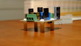
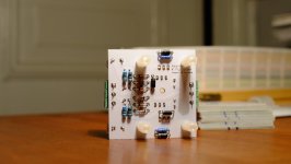
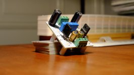
Finally have 2 KCCMs working. One for the DAM R2R DAC and one for JG buffer stage. The DAM draws:
Positive Rail: .18A, 10V
Negative Rail: 0.06A, 10V
Total: 2.4W
so maybe one should bleed the minus side to get the output imp down?
Already they seem to have improved my sound and taken away a little harshness in the top and also made for a more solid foundation in general. Very nice!
Thanks you for your contributions.
//
Attachments
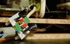
I should say also that they filter these:
https://www.meanwell-web.com/en/pro...y/enclosed-type/0-40-w/rs-15/product/RS-15-24
//
https://www.meanwell-web.com/en/pro...y/enclosed-type/0-40-w/rs-15/product/RS-15-24
//
The output circuit uses intentional feedback to reduce output impedance. The filter circuit has no intentional feedback. It doesn't have to have global feedback to be a filter, you can just use one transistor and that removes the feedback and the low output impedance (and gives you an ordinary C-multiplier).
Thanks for info - we are have a bit of a 'discussion' here about using a CMx or a KMx to the B+ rail of the valve amp input stage (an 845) - a resistance to anything more complicated than simple R, L, C filters is so ingrained, it seems, that not willing to try these out.
Max input ripple before saturation: 1.5V pk-pk (0.46Vrms on an AC multimeter)
It means k-multiplier filters cant be used if there is a 2V drop across the filter capacitors ?
Right now i am powering 8 opamps via 337/317 regulators. Transformer is 6VA, two windings.
WITH no LOAD: +/-31V DC before the regs.
WITH LOAD: 28.8V DC before the regs.
Note: Load is constant (34mA from the Regulators output to the opamps)
Is it good idea to try k-multiplier filter in that setup ?
- Home
- Amplifiers
- Power Supplies
- Keantoken's CFP cap multiplier