I leave 470m OHM resistors in place then ?
Xformer is 170mA AC per winding totalling 2x170mA.
2x18V AC, after rectification without load = ~31V DC
I will use ~2k ohm as a bleeder to get current close to 10mA on both rails + opamps will draw ~35mA, it should do the work i guess.
EDIT: Keantoken specifies that these filters wont do any good if current is less then ~25mA.
Last edited:
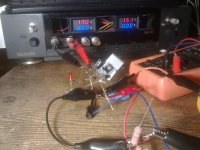
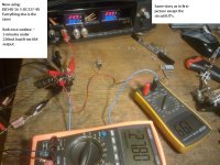
Build the positive side for prototype. Transistors used: BD138G and BC549C and 1000uF 0.06R ESR capacitor instead a 820uF.
On turn on, LED flashes once and than slowly vanishes away.
Seems it works correctly, output impedance is low due to zero voltage variations if load current is changed from 45ma to 140mA.
Voltage drop is 2.05V when the load is given, without load the drop is 1.6V.
Small meter shows current sinking from output "mA"
INPUT ~17V, output ~15V.
Attachments
Last edited:
I got the excellent Dirty boards. Allow stuffing and resting.
When I stuffed one board, I omitted the R1 47 (or 100 ohms) resistor: still it worked well, but of course not as low a output impedance as with 15 ma extra though the BC337.
The config without a R1 is the same as I have in my LeMonstre power amplifiers...
albert
When I stuffed one board, I omitted the R1 47 (or 100 ohms) resistor: still it worked well, but of course not as low a output impedance as with 15 ma extra though the BC337.
The config without a R1 is the same as I have in my LeMonstre power amplifiers...
albert
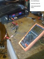
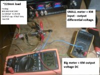
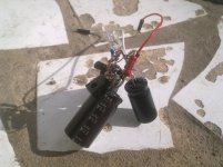
I have build another one(positive), with random 1N4148 diodes, 1000uF 200mR caps, Q1 BC337-40 PH59 and Q2 FairChild BD-140-16.
Everything is stock(default dummy load ~25mA):
across 3 1N4148 i get 1.7V drop
When working with 29.80V input, across R2(1K) i get 38mV drop.
Output - input voltage differential : 2.04V(takes a ~minute to settle down)
Applieng 160mA load to the output increases voltage drop on R2 to 43mV.
Is everything working correctly ? Going to adapt them soon in preamp psu circuits
Last edited:
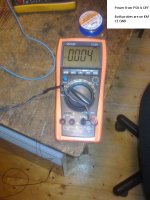
Sounds good so far. It passes all the tests except the test that's left, which is how well it blocks input noise. This might be a problem with the BD140.
If you don't mind, please post the following measurements.
1: Get your most sensitive voltmeter (mV accuracy at least) and set it to ACV. Twist the probes together and put the negative probe at the ground pin of C1. Put the positive probe on the negative probe, wait for the measurement to settle and record the value.
2: Put the positive probe at the input of the KM and measure the ACV.
3: Put the positive probe on the output of the KM and measure the ACV.
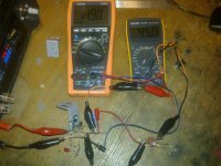
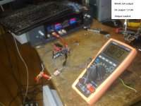
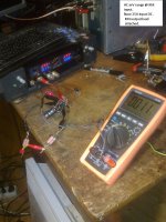
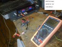
I made some measurements. All info is on the photos.
- First two pics are comparison between BD140-16 and BD138G builds.
- Rest of the pics are taken on AC mV range set to manual.
- DC measurements are accurate..
- AC measurements are questionable or not, you decide please.
Attachments
-
 KM output 27.8V.jpg292.3 KB · Views: 397
 -
 KM INPUT 29.9V.jpg319.4 KB · Views: 448
 -
 A BD140-16.jpg326.4 KB · Views: 499
 -
 A BD138G.jpg234.2 KB · Views: 510
 -
 KM input 25V.jpg356.8 KB · Views: 400
 -
 KM output 23V.jpg315.7 KB · Views: 88
 -
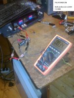 POWERED ON AC.jpg298.9 KB · Views: 93
 -
 NO POWER AC.jpg292.9 KB · Views: 96
 -
 PCB.jpg549.6 KB · Views: 119
Last edited:
Yep, i re-checked PSU on or OFF, tried LM317 based PSU, same results(ACmV increasing when PSU turned on)
Ignore those measurements please.
While comparing BD140 and BD138G, i will go with the first BD140 builds.
First i will try them before the current regulator from apexaudio. Then i will test after the LM317AT & LM337AT psu right at preamp PSU pins.
Ignore those measurements please.
While comparing BD140 and BD138G, i will go with the first BD140 builds.
First i will try them before the current regulator from apexaudio. Then i will test after the LM317AT & LM337AT psu right at preamp PSU pins.
- Home
- Amplifiers
- Power Supplies
- Keantoken's CFP cap multiplier