IG,
Thanks for the feedback. I am surprised that this double-connected-waveguide construct actually works! I am encouraged by your comments about deep bass being an issue with Karlsons - as I thought that may have been a flaw in the model. Does the impedance plot look similar to what you see in a Karlson? That is perhaps one of the best tell-tale signs if the model is close to reality. Anyhow, I am feeling really good about AkAbak's ability to model just about anything you can throw at it. If you have any frequency response or impedance measurements of your Karlson to share that would be appreciated.
Thanks,
X
Regarding your K15 impedance trace, its general form is fairly good, though the rear-chamber should tune around 45Hz I believe (1st impedance minima) and the front chamber ~115Hz IIRC (2nd impedance minima).
Here is the only impedance I ever measured on my K12 "Karlsonette", with manual data points every 2Hz IIRC. Red trace was Richard Allan CG10T and blue Philips AD9710.
Tunings for this K12 are 60Hz/155Hz. I believe that drivers should have a mass-corner slightly above the tuning of the front chamber.
IG
Here is the only impedance I ever measured on my K12 "Karlsonette", with manual data points every 2Hz IIRC. Red trace was Richard Allan CG10T and blue Philips AD9710.
An externally hosted image should be here but it was not working when we last tested it.
Tunings for this K12 are 60Hz/155Hz. I believe that drivers should have a mass-corner slightly above the tuning of the front chamber.
IG
Last edited:
Here is a measurement of the small SK8 with FF225WK and a small 90° conical horn I made for the HF:
Here is a ground-plane of the same, with two vent sizes:
This one has a curved reflector, was a PITA for me to make:
Here is a ground-plane measurement of the K12 with Celestion TF1020 midbass:
In-room response of the same:
That W-effect is apparent in the above graphs, shifted according to enclosure size.
For kicks, here's how a small K5 (actually X5 with internal waveguide) did:
IG
An externally hosted image should be here but it was not working when we last tested it.
Here is a ground-plane of the same, with two vent sizes:
An externally hosted image should be here but it was not working when we last tested it.
An externally hosted image should be here but it was not working when we last tested it.
This one has a curved reflector, was a PITA for me to make:
An externally hosted image should be here but it was not working when we last tested it.
Here is a ground-plane measurement of the K12 with Celestion TF1020 midbass:
An externally hosted image should be here but it was not working when we last tested it.
In-room response of the same:
An externally hosted image should be here but it was not working when we last tested it.
An externally hosted image should be here but it was not working when we last tested it.
That W-effect is apparent in the above graphs, shifted according to enclosure size.
For kicks, here's how a small K5 (actually X5 with internal waveguide) did:
An externally hosted image should be here but it was not working when we last tested it.
An externally hosted image should be here but it was not working when we last tested it.
IG
Last edited:
The front chamber is to be viewed as a perpendicular impedance matching stub, as per JEK's vision; he was an antenna guy afterall.
I had to dig through the backpages of my Imageshack account to find the above pictures and responses, I found this while on there:
I re-drew the Fostex BK-10 into a Karlson, keeping everything the same as much as possible: compression chamber size, throat size, path length/expansion and mouth size. I have no idea how that would perform, but it could be cool. I still have a pair of FF125K. Maybe I could FC-it-up someday, as I had done for the actual BK-10.
IG
I had to dig through the backpages of my Imageshack account to find the above pictures and responses, I found this while on there:
An externally hosted image should be here but it was not working when we last tested it.
I re-drew the Fostex BK-10 into a Karlson, keeping everything the same as much as possible: compression chamber size, throat size, path length/expansion and mouth size. I have no idea how that would perform, but it could be cool. I still have a pair of FF125K. Maybe I could FC-it-up someday, as I had done for the actual BK-10.
IG
Here was a vaguely-related concept, inspired from the old R-J enclosure:
No clue if that would "hold water".
IG
An externally hosted image should be here but it was not working when we last tested it.
No clue if that would "hold water".
IG
Those do look very right for K15 with Kappa12. (I built my first with a DeltaPro12)
--------------------
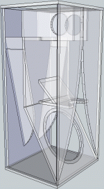
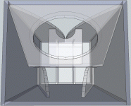
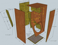
Here's one I dreamed up on a hunch with no scientific basis and never built.
Wonderering if its possible to model by your method or not?
At least I have internal dimensions to work with, not just a rough outline.
Sized for an 18 I would assume....
--------------------
Here's one I dreamed up on a hunch with no scientific basis and never built.
Wonderering if its possible to model by your method or not?
At least I have internal dimensions to work with, not just a rough outline.
Sized for an 18 I would assume....
Attachments
Kenpeter,
That's good news to hear that the response looks correct for K15 with a Kappa. Your design looks pretty neat and should get you lower bass as there is an extra folded line in the back chamber. What is the purpose of the piece of wood and angled plate in the front chamber that is behind the K-slot? Is that just a brace and to be ignored for the purposes of the acoustical path?
That's good news to hear that the response looks correct for K15 with a Kappa. Your design looks pretty neat and should get you lower bass as there is an extra folded line in the back chamber. What is the purpose of the piece of wood and angled plate in the front chamber that is behind the K-slot? Is that just a brace and to be ignored for the purposes of the acoustical path?
Ignore what?
My question, it made no sense, long day etc
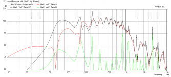
Tangband 15 woofer K15 - think vent area was 30.5 sq.in.
Altec 604 in K15 with 30.5 sq.in. vent
~ ground plane (my yard dropped off sharply) - with 15, ground plane is 30 degrees below the central driver axis
Blue = 40 sq.in. vent K15 with EV15L - Violet = Altec 416 in K15 with 30.5 sq.in. vent
K15 ground plane with EV SP15A
K15 - mic near the center of the cone - null is below system tuning
K15 vs a bass reflex the size of K15's rear chamber and Fb - Two tone modulation comparison with Beta 15cx
An externally hosted image should be here but it was not working when we last tested it.
Altec 604 in K15 with 30.5 sq.in. vent
An externally hosted image should be here but it was not working when we last tested it.
~ ground plane (my yard dropped off sharply) - with 15, ground plane is 30 degrees below the central driver axis
Blue = 40 sq.in. vent K15 with EV15L - Violet = Altec 416 in K15 with 30.5 sq.in. vent
An externally hosted image should be here but it was not working when we last tested it.
K15 ground plane with EV SP15A
An externally hosted image should be here but it was not working when we last tested it.
K15 - mic near the center of the cone - null is below system tuning
An externally hosted image should be here but it was not working when we last tested it.
K15 vs a bass reflex the size of K15's rear chamber and Fb - Two tone modulation comparison with Beta 15cx
An externally hosted image should be here but it was not working when we last tested it.
the 25Hz spike and noise on the K15 trace above was because I had forgot to turn off a window air conditioner ~50 feet away - duh. K15 might play pretty well with BetsyK or BG20. The old (1954 design) K12/"Karlsonette" did well with BetsyK and FE206EN - latter sounded better than my Klipschorns.
Freddi,
Can you send me T/S params for either the EV or Altec drivers, and any details about the K15 cabinet dimensions? It sounds like your vent is enlarged to 30.5 sq in (42% larger than stock). What is meant by front shelf and rear gap dimensions? I want to see if having good dimensions will make the sims match your measurements more. A sketch would be helpful.
Thanks
X
hi xrk971
early but undated K15 drawings showed a 32 sq.inch vent - but ~40 sq. inches (4.5" x 9") for the January 1954 Radio and Television News article. In 1956 the vent was narrowed again and shelf gaps tightened ("changeover mod")
K15 and likely the K18 were the only production K-coupler to use a front shelf - by autumn 1954 the first K12 had been introduced ("Karlsonette") - the Karlsonette had a 3-position adjustable rear lowpass gap accomplished by a movable bar in proximity to the fixed rear shelf.
if the front shelf were left out of K15, I think the first hole would be deeper.
smaller and more shallow couplers won't need the front deflecting piece - it can deflect some energy from reaching the upper part of the front coupler . I do think it would work in a 0.8 scale K15 if shortened a bit.
it would be nice if you could offer a model sans the front shelf.
EVM15L Fs=43hz ,Vas=0.245m3 , Qts=0.238 , Qms=4.96, Qes=0.25, Re = 5.2 ohm, Sd = 855.3 cm2
K15 by Carl's estimation
vf (front chamber) = 2.3 cu ft
vb (rear chamber) = 4.0 cu ft
sb (inner vent) = 32 sq inches (after 1956 changeover - 1954 vent was 40 sq. inches)
sf (aperture area) = 222 sq inches
The rear shelf creates a port area of 52.5 sq inches with the back of the cabinet. This area is sometimes smaller and can be tweaked with good recordings of drum and plucked bass viola.
The front shelf creates an area of 73.5 sq inches with the wings.
K15 plan from January 1954
http://img825.imageshack.us/img825/5469/k15k.png
Freddi,
What does the 0.46 in gap refer to in the K15 with the EV?
I think that would be the starting width of the K-slot. It's often around 0.5" and all other gaps I can think of are spoken for on that particular graph.
The Karlson lexikon kan be kwite konfusing to newkomers.

IG
Sim of 1954 K15 with EV driver
Freddi,
I put in the cabinet dimensions from the link you provided. They are significantly different than the version that I used in the first model provided by Job Ulfman at http://home.planet.nl/~ulfman/
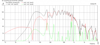
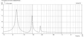
It made the bass sag a bit. Anyhow, with the 40.5 sq inch vent and shelfs at distances you specify with EV driver, mic at 2 m away on the ground, here is what I get. I seem to be getting a dip at 130 Hz that is not in your measurements. The location of the W is about right though. Second plot is the impedance.
Third plot is sans front shelf.
Freddi,
I put in the cabinet dimensions from the link you provided. They are significantly different than the version that I used in the first model provided by Job Ulfman at http://home.planet.nl/~ulfman/
It made the bass sag a bit. Anyhow, with the 40.5 sq inch vent and shelfs at distances you specify with EV driver, mic at 2 m away on the ground, here is what I get. I seem to be getting a dip at 130 Hz that is not in your measurements. The location of the W is about right though. Second plot is the impedance.
Third plot is sans front shelf.
Attachments
Last edited:
- Home
- Loudspeakers
- Full Range
- Karlson