Hartmut:
There are many people in the world, and each one has different priorities and tastes. This is why there are many different audio designers, painters, chefs, and so on. There is zero likelihood than any one design will satisfy everyone. I don't think that it is wise to even _try_ to satisfy everyone.
The perceived noise floor was likely just as much a gain issue as a noise issue. Because the gain of the Connoisseur is very high (even the line preamp gain is 35dB), any noise entering or existing in the system is amplified very much. Proper system power bussing and grounding practices will minimize this tendancy and will also insure that the resolution potential (of any component) is fully realized. OTOH, audiophiles who understand these issues and implement correct power and ground bussing techniques in their audio systems are exceedingly rare. In the future, I may add technologies to the Connoisseurs that insure that, even if they are installed and used incorrectly in an audio system, they won't voice their displeasure quite so vocally
To design deliberately for lowest noise would mean extending the bandwidth as little as possible and using the lowest-noise devices available. Ultra-low-noise devices almost always have large surface areas and quite a bit of capacitance. Along with lower noise, the result would be less resolution (and the smaller bandwidth).
In contrast to the above, I try for very low intermodulation with very wide bandwidth, and try to get the noise as low as possible within that framework. This way, the resolution and phase response will be excellent, and even if there is noise, it will be decoded in a different manner from the musical signal, and should therefore be very easy to ignore. I personally think that the latter approach does less damage to the music than designing for the lowest possible noise floor.
But in any case, I think that we are talking about philosophically different design approaches, and a choice between poisons.
>I always thought you had 100mS custom JFETs in the input.<
100mS? Like some of the higher gfs Toshiba JFETs? That would be a capacitive monstrosity. Quiet, slow, low resolution, with instrumental timbres that sound like they are reproduced in black and white instead of color. Not my cup of tea. Yes we use special JFETs, but these have much less transconductance than 100mS - perhaps a quarter of that.
best, jonathan
PS. Frank Schroeder has had the Connoisseurs at home, and based on my observations of how he sets up an audio system and listens, I consider his comments insightful and worth heeding. Nonetheless, the Connoisseurs brought to Germany have all been from much earlier production, so it is likely that if Frank were to listen to the latest specification, he would get a somewhat different impression.
PPS. I am sure that I will get to Munich one day, and when I do, music, beers and conversation with you and Willi sounds like an excellent idea!
Jonathan,
it was Chris who said something against your preamp and Frank who said something in favour of your preamp. Don't mix it up. I just sent you some more information with email.
Hmm, the 100mS I just guessed from the conversation with you about your preamp when we were on Analogue Addicts mailing list some years back. Maybe I just deducted too many things from the puzzle parts you gave me as food for thought.
I tried a lot of JFETs, and there are a lot of trade-offs when choosing the parameters. While I like low capacitance devices like 2SK97 for their treble and mid performance, I prefer higher gm types for bass performance. And types with both high gm and low capacitance seem to have poor output impedance, poor DC stability, higher 1/f noise.
So, I am curious to see more specs of your input JFETs.
I am looking forward meeting you in Munich.
regards,
Hartmut
Kaneda pre
Hi,
I have built the Kaneda preamp and a JC-2 clone I used components as close to original as I could I even bought the components for the Kaneda from a retailer who hold the Kaneda kit.
Results? the JC-2 clone was much better in any point the Kaneda clone sounds harsh, grainy and cold while the JC-2 clone was warm, detailed and generally exact.
JC-2 Clone
Hi Kamskoma,
Welcome to this forum!. I see this is your first post here.
What components did you use for the JC-2 clone?. Did you adhere to the original schematic as posted on www.marklev.com ?
I did some reverse engimeering of the modules and found other components than in the schematic. Most notably outputtransistors, not FETs, and input FETs.
Also various RIAA correction circuits excist with different soundcharacter!
A AD744 and push-pull output stage is more simple to build and sounds better as line stage, in my opinion.

JC-2 Clone
I used original components from Siliconix I bought 25 of each and run them in a matching jig.
The schematics I used was from TAA but something was wrong with this drawing ? the input stage was a type of smith trigger?? so a friend of mine redesigned it, and it worked.
So you have a design with some type of opamp and some discrete components I'm very interested can you post your design.

JC-2 "Clones"
Hi kamskoma,
Please have a look at this thread:
http://db.audioasylum.com/cgi/m.pl?forum=tweaks&n=35230&highlight=elso+JC-2&r=&session=
and the double diamondoutput buffer (LH0001 style):
http://www.linear.com/pub/document.html?pub_type=app&document=50

Hi kamskoma,
Please have a look at this thread:
http://db.audioasylum.com/cgi/m.pl?forum=tweaks&n=35230&highlight=elso+JC-2&r=&session=
and the double diamondoutput buffer (LH0001 style):
http://www.linear.com/pub/document.html?pub_type=app&document=50

The JC-2 preamp
Hi Elso Kwak,
Thank you for the links but I don't really need them as I'm a rabiate follower of a movement, follow the leader he will show you heaven, you se I can't se myself doing hifi with ic op amp my heart should burn in hell if I come too close to IC's.
Sorry but my relegion is in discrete components as I have done succes with my clone of the JC-2.
But if we could find some parts substitute for the semiconductors I would be very happy maybe even try to get a better design for the output, lower impedance.
I don't use the RIAA part in John's design maybe there is some better discrete designs somwhere here on this forum?.
IC vs. Discrete Design
Hi kamskoma,
Quite frankly I am not the type of following a leader...
But agree with you that a discrete design can be better than IC.
However the room in the modules is so small that I decided to use a IC and only a discrete outputstage. At the time of posting at AA I was using IC's as inputstage. Later I placed FET's in front of the IC and eventually totally discarded the IC. And I am also not a follower in using very narrow traces. My present folded cascode design takes a lot more boardspace.
I am a bit puzzled by your latest post where you express a dislike of IC-design and one post earlier you say that you are very interested and asked me to post my opamp design with some discrete components ....
This last one #3 from 1985 RIAA
This last sample, RIAA from 1985,
I think is a very nice amplifier.
Maybe I should try it ....

It is for MC Moving Coil Pickup,
so I have to modify it. Input Impedance and so.
Anyway, thank you, tvi
I have copied them to my harddisk.
/halo - still some GigaBytes to go .....
This last sample, RIAA from 1985,
I think is a very nice amplifier.
Maybe I should try it ....
It is for MC Moving Coil Pickup,
so I have to modify it. Input Impedance and so.
Anyway, thank you, tvi
I have copied them to my harddisk.
/halo - still some GigaBytes to go .....
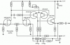
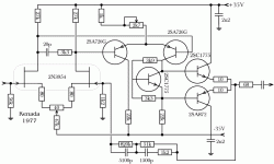
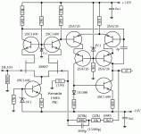
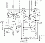
It is interesting to note that none of the three amps have any
decoupling caps except at the rails. There are a number of
places where it migt seem sensible to add a cap, eg. in parallel
with the zener diodes for CCSes and cascodes. Does anybody
know if Kenada was an early anti-capacitor guy or if he just
didn't think it necessary to use more caps?
decoupling caps except at the rails. There are a number of
places where it migt seem sensible to add a cap, eg. in parallel
with the zener diodes for CCSes and cascodes. Does anybody
know if Kenada was an early anti-capacitor guy or if he just
didn't think it necessary to use more caps?
Christer: Kaneda (not Kenada, BTW) was a stickler for details, and he specified pretty much everything in a circuit that he felt mattered. Semiconductors, circuit boards, capacitors, resistors, batteries, switches, and so on. His favorite resistors were "Skelton" and also the flat-plates by Susumu, while he liked the SE stacked-mica and the V2A, both by Soshin.
I believe that overall he was against electrolytic capacitors, preferring film caps and battery power supplies. It is likely that he was more willing to tolerate the noise of the Zeners than the sound of electrolytic caps.
In recent years, however, you can see that his circuits are clearly designed to be simpler and easier to build. Perhaps Kaneda is becoming more mellow and less picky as he gets older
regards, jonathan carr
jcarr said:Christer: Kaneda (not Kenada, BTW) was a stickler for details, and he specified pretty much everything in a circuit that he felt mattered. Semiconductors, circuit boards, capacitors, resistors, batteries, switches, and so on. His favorite resistors were "Skelton" and also the flat-plates by Susumu, while he liked the SE stacked-mica and the V2A, both by Soshin.
I believe that overall he was against electrolytic capacitors, preferring film caps and battery power supplies. It is likely that he was more willing to tolerate the noise of the Zeners than the sound of electrolytic caps.
In recent years, however, you can see that his circuits are clearly designed to be simpler and easier to build. Perhaps Kaneda is becoming more mellow and less picky as he gets older
regards, jonathan carr
Thanks, Jonathan. Yes, I suspected that was the reason, but
it is nice to get facts instead of speculations.
BTW, I had always thought the name was Kaneda, but since it
said Kenada in the schematics, I assumed obvoisly incorrectly,
that this was the correct Spelling.
Re: Another error in schematic no.3
If you raise resistor from 180k to 270k,
you have to lower parallell cap. To keep the RxC at same value.
From 2600p to 1530p.
(Or should it be from 26000p to 15300p, in that case it is 2600p that is wrong)
halo
Yes, something is wrong.hifidaddy said:besides writing the name Kaneda wrong in schematic no.3, there is another error in the circuit. Have a look at the both alternative active RIAAs EQs. A cap of 1530pF would surely fit better than a 15300pF, wouldn't it ?
regards,
Hartmut
If you raise resistor from 180k to 270k,
you have to lower parallell cap. To keep the RxC at same value.
From 2600p to 1530p.
(Or should it be from 26000p to 15300p, in that case it is 2600p that is wrong)
halo
- Status
- This old topic is closed. If you want to reopen this topic, contact a moderator using the "Report Post" button.
- Home
- Source & Line
- Analog Line Level
- kaneda preamp


