Kanéda preamp by Jean Hiraga
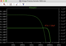
here is my try on modelling of the Kanéda preamp circuit; I have not the appropriate LTSpice models of the old Japanese transistors so I have used some at hand. The 2SK170 might come close to the 2SK240 I have (but not in Idss but in this config that is of no issue I think, but I really should use a model for the 2SK30AGR. [Who has that??]
I used generic transistors instead of the Japanese ones. They probably fit the picture.

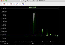
The harmonic degradation is a charm to see, and this is at 14 dB out (0 in)

I will try to use different output device.
here is my try on modelling of the Kanéda preamp circuit; I have not the appropriate LTSpice models of the old Japanese transistors so I have used some at hand. The 2SK170 might come close to the 2SK240 I have (but not in Idss but in this config that is of no issue I think, but I really should use a model for the 2SK30AGR. [Who has that??]
I used generic transistors instead of the Japanese ones. They probably fit the picture.

The harmonic degradation is a charm to see, and this is at 14 dB out (0 in)

I will try to use different output device.
Attachments
Last edited:
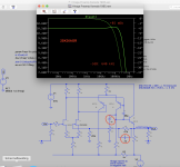
I found a good 2SK30 model and here is the result:

No low pass in the feedback yet.
A formidable result. 0Hz - 640 kHz
I think that using the 2SK170 (I have the 2SK240 for the RIAA) should probably require an adaption of the R1, R2, R4 resistors in the input section to get the same wide bandwidth result.
Distortion: at 6 dB output, -100 dB second, -120 dB third, no higher harmonics.
This is thanks to EUVELs nice sim settings I can assure you.
When adapting the Maison de l'Audiophile boards I have had similar results by the way (I shortcircuited one line board populated with the original transistors, impossible to find the same; choose to change to older metal can types.
- Tested these older transistors a lot. On the testbench, without compensation, a simple high band without any peaks. So indeed it is possible.
Last edited:
Could you share the 2sk30 model?
I have used this LTSpice-model, that holds a section for the different versions; Hiraga requiring the AGR version:
*2SK30
*id(R 0.3-0.75 / O 0.6-1.4 / Y 1.2-3.00 / GR 2.6-6.5)
.model 2SK30r NJF(vto=-0.8v beta=0.75m lambda=0 cgd=2.6p cgs=8.2p
+ dev 10% LOT 60%)
.model 2SK30o NJF(vto=-1.1v beta=0.75m lambda=0 cgd=2.6p cgs=8.2p
+ dev 10% LOT 60%)
.model 2SK30y NJF(vto=-1.8v beta=0.75m lambda=0 cgd=2.6p cgs=8.2p
+ dev 10% LOT 60%)
*2SK30AGR
.model 2SK30AGR NJF(vto=-2.8v beta=0.75m lambda=0 cgd=2.6p cgs=8.2p
+ dev 10% LOT 60%)
.model 2SK30atm NJF(beta=.768m vto=-2.70 cgd=2.6p cgs=8.2p dev 10% LOT 60%)
* CQ 1988/7
Hello Al,
please try this model :
.MODEL 2SA1316 PNP (IS=10.1F NF=1 BF=910 VAF=161 IKF=60M ISE=1.11P NE=2 BR=4 NR=1 VAR=20 IKR=90M RE=3.15 RB=12.6 RC=1.26 XTB=1.5 CJE=45.5P VJE=1.1 MJE=.5 CJC=14.6P VJC=.3 MJC=.3 TF=3.18N TR=2.21U Vceo=80 Icrating=0.1A mfg=Toshiba
.MODEL 2SC1213 NPN
+IS=210.0E-15 BF=150 NF=1 VAF=20 IKF=500.0E-3 ISE=130.0E-12
+NE=2 BR=25 NR=1 VAR=70 IKR=240.0E-3 ISC=1.650E-9 NC=2
+RB=700.0E-3 IRB=20.00E-3 RBM=816.0E-3 RE=125.0E-3 RC=26.00E-3
+XTB=0 EG=1.11 XTI=3 CJE=270.0E-12 VJE=680.0E-3 MJE=332.0E-3
+TF=1.5E-9 XTF=20 VTF=100 ITF=9 PTF=0
+CJC=54.50E-12 VJC=500.0E-3
+MJC=373.0E-3 XCJC=1 TR=1.000E-9FC=500.0E-3 KF=0 AF=1
With this models I have close value at Q1 collector voltage 602 mV, trim R3 value about 9104 ohm then I got the same voltage at Q2 collector.
I played with your asc file and I change this .four {Freq} V(VUIT) 5 5 .
Have a good day.
Best Regards,
Josh
I have used this LTSpice-model, that holds a section for the different versions; Hiraga requiring the AGR version:
Thank you!
With the new models and transistors and no comp on the feedback - only C3 68pF- , I simulate -3dB at 987 kHz, up from 640 kHz.
Clearly these models fit better as a whole. The distortion is practically the same.
When rebuilding, I will get the circuit close to zeroV out, then with the potmeter R9/R19 (100 ohms) I will go for the best distortion (negative 2nd); reset output.
Clearly these models fit better as a whole. The distortion is practically the same.
When rebuilding, I will get the circuit close to zeroV out, then with the potmeter R9/R19 (100 ohms) I will go for the best distortion (negative 2nd); reset output.
- I used to have a tube version of the symetrical preamp; that gave some 4-5% 2nd, best sounding I had. [Was microphonic so I binned it]
RIAA section modelled
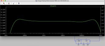
And here I have the RIAA section using 2SK30AGR.
We see a low boost that is sensitive to the first transistor: with 2SK170 it is higher! Also with the 2SK30AGR it is lower than with 2SK30A_GR (two different model values).
This also depends on the output capacitor of course, here it becomes clear why Hiraga said to use a 400nF output to a 50 k pot.
Hiraga liked the slight low boost; he wrote about this in the article with a tube RIAA version that has the same feedback filter.
The model needs some more study I think. For instance, in the model, taking out C3 and C5 tilts the slope more straight but give rise to nasty HF resonances.

So enjoy.
And here I have the RIAA section using 2SK30AGR.
We see a low boost that is sensitive to the first transistor: with 2SK170 it is higher! Also with the 2SK30AGR it is lower than with 2SK30A_GR (two different model values).
This also depends on the output capacitor of course, here it becomes clear why Hiraga said to use a 400nF output to a 50 k pot.
Hiraga liked the slight low boost; he wrote about this in the article with a tube RIAA version that has the same feedback filter.
The model needs some more study I think. For instance, in the model, taking out C3 and C5 tilts the slope more straight but give rise to nasty HF resonances.

- as ultimate remedy, the pair C4/R14 can be adapted to get a more straight HF. But I would not start tinkering there . . .
This filter has a fairly accepted following! And it sounded great with my 2SK240. Indeed, lively sound stage, depth and width of a studio.
So enjoy.
Attachments
Last edited:
Hiraga liked the slight low boost
+0.7db hardly qualifies as slight. And this sloping riaa characteristic just seems wrong.
For some reason i find deviations in riaa very audible and usually objectionable. Yes, trivial to correct, but very strange it was designed like that in the first place. Perhaps it equalised his speakers.
+0.7db hardly qualifies as slight. And this sloping riaa characteristic just seems wrong.
For some reason i find deviations in riaa very audible and usually objectionable. Yes, trivial to correct, but very strange it was designed like that in the first place. Perhaps it equalised his speakers.
I am surprised by the outcome myself . . .
Maybe I did something wrong?

Here some tinkering:

Last edited:
Member
Joined 2009
Paid Member
+0.7db hardly qualifies as slight. And this sloping riaa characteristic just seems wrong.
For some reason i find deviations in riaa very audible and usually objectionable. Yes, trivial to correct, but very strange it was designed like that in the first place. Perhaps it equalised his speakers.
I believe other designs would be found to be not meeting the ideal, a form of ‘voicing’, with Sakuma’s work perhaps an extreme example.
In his article "Préamplificateurs à tubes. Des grands classiques aux dernières évolutions.", in L'Audiophile nr 21, sept 1981, Jean Hiraga elaborated a lot on the classical RIAA amplifiers.
One of these circuits is the Audio Research SP3. The later Kanéda version in solid state uses the same feedback values as the SP3. He is aware of the slight tilt. The SP3 RIAA is about 2 dB higher at 20 Hz than the Marantz 7 and almost 1 than the MacIntosh C22.
He discusses this one against the others:
Yes, you can call it 'voicing'.
The 1K5 in series with the 1n5 is for adapting, high frequency adaptation. In the SP3 it is 1K. It has a slight effect at 20 kHz.
Error in my simulation diagram: I placed a 68 pF on the wrong leg of the second stage. It should be on the leg that is not loaded by the output.
My line level is up and running again, it gives a very nice square wave. No overshoot, no HF at any moment.
One of these circuits is the Audio Research SP3. The later Kanéda version in solid state uses the same feedback values as the SP3. He is aware of the slight tilt. The SP3 RIAA is about 2 dB higher at 20 Hz than the Marantz 7 and almost 1 than the MacIntosh C22.
He discusses this one against the others:
"contrary to what one might think, a correction curve that does NOT drop in the extreme lows, and steadily rises a bit towards at least 15 Hzcompensates for a large part the subjective shortcomings [of loudspeakers] without for one instant giving the impression of the bass 'going lower'. "
"the Marantz 7 has a different sonority, is looser, more pleasant. One does note that the circuit on the other hand drops quickly below 40 Hz, [] This gives rise for some boominess in the low which leads to the sound loosing its precision."
Yes, you can call it 'voicing'.
The 1K5 in series with the 1n5 is for adapting, high frequency adaptation. In the SP3 it is 1K. It has a slight effect at 20 kHz.
Error in my simulation diagram: I placed a 68 pF on the wrong leg of the second stage. It should be on the leg that is not loaded by the output.
My line level is up and running again, it gives a very nice square wave. No overshoot, no HF at any moment.
Marantz 7C is given as (680k//5600pF) + (47k//(1600pF+1k)). In my notes there is a 22pF [Phantom??=board capacitance?] across this whole section.
Hiraga also mentions the positive feedback of the PAS-X (that I built at that time) and the C22; he uses it for his tube RIAA too - it increases the dynamics and linearises the high. I have never seen such a device in a solid state preamplifier.
Hiraga also mentions the positive feedback of the PAS-X (that I built at that time) and the C22; he uses it for his tube RIAA too - it increases the dynamics and linearises the high. I have never seen such a device in a solid state preamplifier.
- Status
- This old topic is closed. If you want to reopen this topic, contact a moderator using the "Report Post" button.
- Home
- Source & Line
- Analog Line Level
- kaneda preamp