an added note
Prasimix,
since you know I will use the board to bridge amps I wanted to throw in an added explanation: I will likely use one LSK channel as the phase splitter, then take Out+ and Out- signals each to its own buffer (so one LSK channel followed by two buffers). Can you please check if the board provides for a reasonably neat way to make this connection? thanks.
p.s.> btw I am likely to take 5 dual channel (stereo version) boards. Thanks. (this is up from 3 which i said last time") .
.
Prasimix,
since you know I will use the board to bridge amps I wanted to throw in an added explanation: I will likely use one LSK channel as the phase splitter, then take Out+ and Out- signals each to its own buffer (so one LSK channel followed by two buffers). Can you please check if the board provides for a reasonably neat way to make this connection? thanks.
p.s.> btw I am likely to take 5 dual channel (stereo version) boards. Thanks. (this is up from 3 which i said last time
.Prasimix,
since you know I will use the board to bridge amps I wanted to throw in an added explanation: I will likely use one LSK channel as the phase splitter, then take Out+ and Out- signals each to its own buffer (so one LSK channel followed by two buffers). Can you please check if the board provides for a reasonably neat way to make this connection? thanks.
p.s.> btw I am likely to take 5 dual channel (stereo version) boards. Thanks. (this is up from 3 which i said last time
I think that could be a very simple task. Let's assume that you'll use "upper" channel from your dual channel PCB as phase splitter (schematic in post #89). "Upper" buffer is already connected to one half of the splitter. Another half you can bring to other buffer from OUT2A pin #1 to OUT2B pin #2. That's all.
EDIT: On existing dual channel PCB it's possible to introduce one optional jumper to make above mentioned connection.
Last edited:
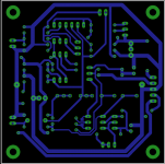
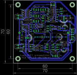
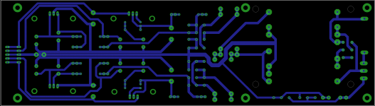
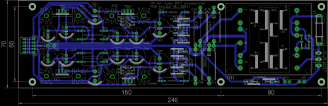
Here is I hope the final layouts of all three PCBs. I'll leave then for couple of days and if nothing new is popped up, I think that's the time for send it to the production.
GB list is pretty on target, and I can assume it closed, thanks everyone for make it happen. I still need destination country from some of you, that I can calculate total cost.
GB list is pretty on target, and I can assume it closed, thanks everyone for make it happen. I still need destination country from some of you, that I can calculate total cost.
Attachments
-
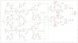 Juma preamp rev.2.6 dual schematic.png143.6 KB · Views: 520
 -
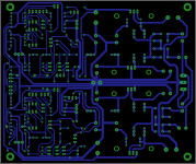 Juma preamp rev.2.6 dual bottom.png90.1 KB · Views: 493
 -
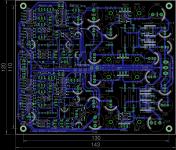 Juma preamp rev.2.6 dual.png196.5 KB · Views: 471
 -
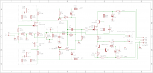 Juma preamp rev.2.9 mono schematic.png56.9 KB · Views: 469
 -
 Juma preamp rev.2.9 mono bottom.png31.1 KB · Views: 454
 -
 Juma preamp rev.2.9 mono.png61.6 KB · Views: 167
 -
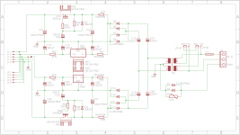 Juma preamp rev.2.6 PS schematic.png57.7 KB · Views: 201
 -
 Juma preamp rev.2.6 PS bottom.png59.4 KB · Views: 184
 -
 Juma preamp rev.2.6 PS.png119.9 KB · Views: 150
 -
Juma preamp rev.2.6 BOM.pdf138.6 KB · Views: 114
I was curious to see that you have sorted out the sizes of the pcbs so that 2 of the gain stage pcbs can fit on top/below the single power supply board - might need a bit of a bracket for the mounting holes near the vertical IRF610/9610 heatsinks, but not very difficult - very neat bit of design.
I know it's a bit late in the day for any more mods but perhaps, as there is mains power on the board anyway, that perhaps it could be possible to extend the end of the board to include a series NTC in the mains input active line - keeps things a lot simpler for mains wiring.
I won't say anything more about extras but the inclusion of a mains dc trap comes to mind altho the primary winding impedance makes it nearly unnecessary (again, IMO).
I was curious to see that you have sorted out the sizes of the pcbs so that 2 of the gain stage pcbs can fit on top/below the single power supply board - might need a bit of a bracket for the mounting holes near the vertical IRF610/9610 heatsinks, but not very difficult - very neat bit of design.
I know it's a bit late in the day for any more mods but perhaps, as there is mains power on the board anyway, that perhaps it could be possible to extend the end of the board to include a series NTC in the mains input active line - keeps things a lot simpler for mains wiring.
I won't say anything more about extras but the inclusion of a mains dc trap comes to mind altho the primary winding impedance makes it nearly unnecessary (again, IMO).
Tried to add it but there is simply no more space for it, sorry.

Hi prasimix,
Thank you for your hard work on these boards.
What is the approximate time scale on these boards please?
Should be 7-10 working days. I let you know when place an order.
btw, is there enough room to ship a board set to Juma ?
To be honest that's something that I intented to ask Juma if he would like to accept 2xsingle+1xPS+1xdual PCB as a gift.
prasimix:
Can you confirm that the BOM has not changed since your version 2.5 (2014-01-19)? I need to identify the corresponding part numbers for Mouser or Digikey and don't want to generate a bad list.
In fact, to make things a little easier, could you post the Excel spreadsheet as opposed to a .pdf? That would simplify adding entries and prices.
Regards,
Scott
Mouser or Digikey and don't want to generate a bad list.
Scott,
If you could post the Mouser/Digikey BOM once you are done that could be very helpful to others (at least for me
).Cheers,
Nic
- Status
- This old topic is closed. If you want to reopen this topic, contact a moderator using the "Report Post" button.
- Home
- Group Buys
- Juma's LSK Preamp - through hole version