Single rail fabrication results
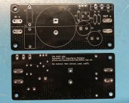
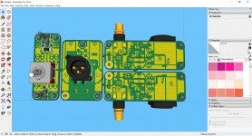
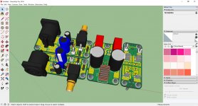
I had the layout at http://www.diyaudio.com/forums/soli...sy-capacitance-multiplier-51.html#post5511885 fabricated at Elecrow. I ordered 10x 1.6mm/1oz/HASL for $5 before shipping (shipping was around $25). All design files, including Gerber and drill can be found at GitHub - oseaudiolabs/adjustable-cap-mx: Adjustable capacitance multiplier PCB.
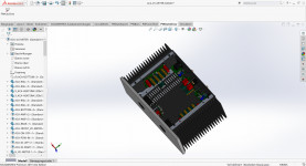
I have not had time to do extensive testing or validation, but I am using it in my MoFo build detailed at http://www.diyaudio.com/forums/pass-labs/313649-build-mofo-139.html#post5531597. There does not appear to be any errors in the fabrication and layout, and the output voltage seems to track with the adjustment of the the trim pot. All of my testing has been with either a lab power supply or a well regulated SMPS, so the effect on power supply ripple has been hard to determine thus far. I did see a decrease in ripple on an SMPS (just using the AC voltage setting on my DMM) from around 4.1mV to 0.98mV at a 1A load. I have load tested up to a 6A on the SMPS without any noticeable issues with heat.
Next, I plan on testing it fed from an unregulated linear power supply. Hopefully this will let me validate a significant decrease in ripple and understand the impact of changes to the R2/RV1/R3 ratios. Does anyone have a better method to identify the actual ripple on the rails? Is using my DMM's AC setting enough or should I be inspecting with a scope?
I had the layout at http://www.diyaudio.com/forums/soli...sy-capacitance-multiplier-51.html#post5511885 fabricated at Elecrow. I ordered 10x 1.6mm/1oz/HASL for $5 before shipping (shipping was around $25). All design files, including Gerber and drill can be found at GitHub - oseaudiolabs/adjustable-cap-mx: Adjustable capacitance multiplier PCB.
I have not had time to do extensive testing or validation, but I am using it in my MoFo build detailed at http://www.diyaudio.com/forums/pass-labs/313649-build-mofo-139.html#post5531597. There does not appear to be any errors in the fabrication and layout, and the output voltage seems to track with the adjustment of the the trim pot. All of my testing has been with either a lab power supply or a well regulated SMPS, so the effect on power supply ripple has been hard to determine thus far. I did see a decrease in ripple on an SMPS (just using the AC voltage setting on my DMM) from around 4.1mV to 0.98mV at a 1A load. I have load tested up to a 6A on the SMPS without any noticeable issues with heat.
Next, I plan on testing it fed from an unregulated linear power supply. Hopefully this will let me validate a significant decrease in ripple and understand the impact of changes to the R2/RV1/R3 ratios. Does anyone have a better method to identify the actual ripple on the rails? Is using my DMM's AC setting enough or should I be inspecting with a scope?
Attachments
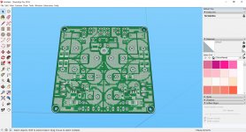
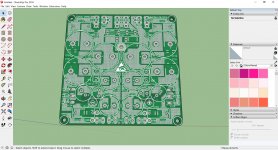
no, I am not going to duplicate the power plane on top. I like the PCB just as is with a contiguous ground plane on top layer. See Mark Johnson's ring not PCB.
It's a pity. I liked the idea of a Frugal Cap-MX.

Yes, that looks like a great option. But if gtose thinks that 1oz is enough for his version, then I could try either layouts with 1oz. I'm not in a hurry. Will watch the developments till I need a Cap Mx again.skylar,
good option for you to get already manufactured and tested pcb from gtose, only if he is willing to share.
Last edited:
It's a pity. I liked the idea of a Frugal Cap-MX.
There is no need for pity.. You can find a custom-solution by finding someone to design pcbs as per your requirements or find out technically if a given pcb is suitable to your requirements
. It can be!It's a pity. I liked the idea of a Frugal Cap-MX.
Yes, that looks like a great option. But if gtose thinks that 1oz is enough for his version, then I could try either layouts with 1oz. I'm not in a hurry. Will watch the developments till I need a Cap Mx again.
Skylar,
If you look at the width of the main current carrying traces, they are about 1/3rd the width of the board. Even with 1oz there is plenty of trace for lots of amps. I have a set on order from JLCPCB - only 1oz but I think it will be fine. PM me if you want a set.
X
Skylar,
If you look at the width of the main current carrying traces, they are about 1/3rd the width of the board. Even with 1oz there is plenty of trace for lots of amps. I have a set on order from JLCPCB - only 1oz but I think it will be fine. PM me if you want a set.
X
You are right, X. Those tracks are huge!
Thanks for the offer. You are too kind. I don't really need a Cap-Mx right now. Just planning for the future... This hobby seems very addictive.
I have a question, though; Are one or two Cap-Mx's required for a 2-channel system?
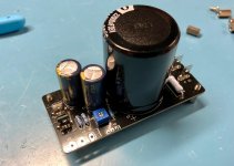
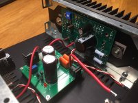
I saw this picture just now of JeffreyD's ACA with a single Allo Cap-Mx. Will it give the same channel separation as dual Cap-Mx's?
Attachments
There is no need for pity.. You can find a custom-solution by finding someone to design pcbs as per your requirements or find out technically if a given pcb is suitable to your requirements
Good point, Prasi.
I can pay someone to do it... or if I'm not so lazy, I suppose I could do it myself. Last year I did my own ACA board layout, but it took a very long time. It came out fine in the end.
.
I saw this picture just now of JeffreyD's ACA with a single Allo Cap-Mx. Will it give the same channel separation as dual Cap-Mx's?
Hi Skylar,
I’m using the same capMx’s for my Big MoFo. One 5A SMPS and one Allo capMx for each MoFo board. Works excellent
Hi Skylar,
I’m using the same capMx’s for my Big MoFo. One 5A SMPS and one Allo capMx for each MoFo board. Works excellent
Thanks for confirming, Vunce. From that I understand that you're using one Allo Cap-Mx for each amp board.
.
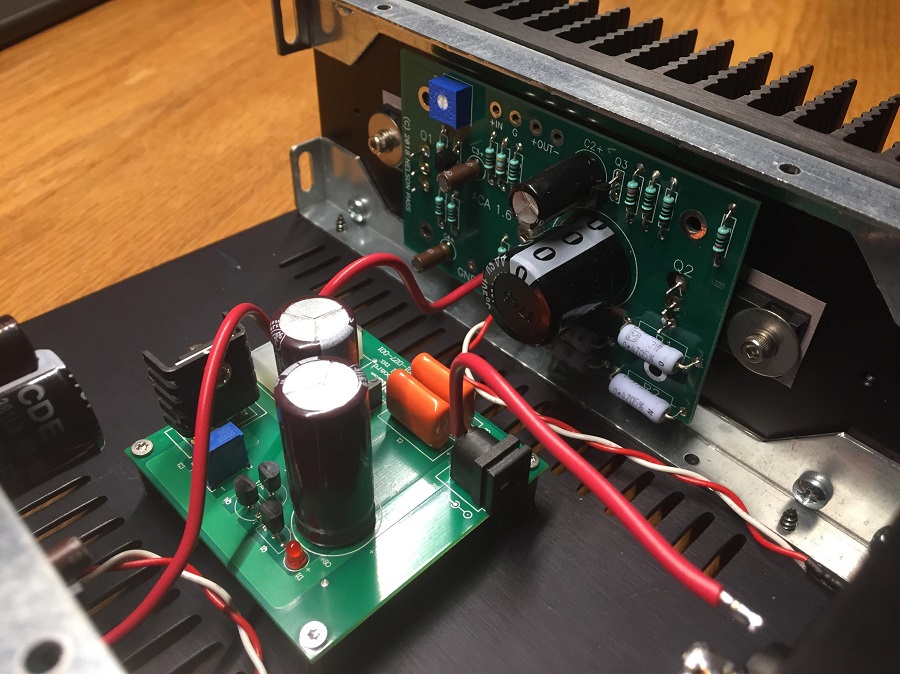
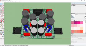
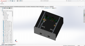
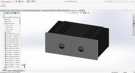
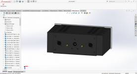
I´ll upgrade my ACA (custom PCB) and MoFo (custom PCB) with capacitor multiplier. I´ve restraint place so I do my own PCB adding CRCRC (3x15000µ) and central grounding.
I´ve also upgraded with little helpers such as CLC SMPS input filter, ON/OFF board and I/O board with VU-Meter interface.
I´ll order 10 boards tomorrow and they´ll be delivered during my 4 week september travel.
After testing, so middle october, I´ll have still 6 boards each left. Tombola to come.
JP
Attachments
Τhere is no doubt that you are a pcb specialist!I´ll upgrade my ACA (custom PCB) and MoFo (custom PCB) with capacitor multiplier. I´ve restraint place so I do my own PCB adding CRCRC (3x15000µ) and central grounding.
I´ve also upgraded with little helpers such as CLC SMPS input filter, ON/OFF board and I/O board with VU-Meter interface.
I´ll order 10 boards tomorrow and they´ll be delivered during my 4 week september travel.
After testing, so middle october, I´ll have still 6 boards each left. Tombola to come.
JP
I am attempting a miniature SMD version of the handwritten schematic in Post 1 and am trying to bring down the voltage drop and increase the efficiency of the circuit.
I've tried 3 FETs so far, ZVN4306G , SQ3456EV, and DMN3027LFG. and got voltage drops of 2v, 2.5v, and 2.3v, respectively.
It seems that optimzing is more complex than just finding FETs with the lowest RDS(on) or VGS(th).
Anyone know of a good SMD FET for the job, with a view on the smaller footprints like SOT23-6 - SOIC8 might be possible but undesirable. Need ~200mA at ~20v.
I am attempting a miniature SMD version of the handwritten schematic in Post 1 and am trying to bring down the voltage drop and increase the efficiency of the circuit.
I've tried 3 FETs so far, ZVN4306G , SQ3456EV, and DMN3027LFG. and got voltage drops of 2v, 2.5v, and 2.3v, respectively.
It seems that optimzing is more complex than just finding FETs with the lowest RDS(on) or VGS(th).
Anyone know of a good SMD FET for the job, with a view on the smaller footprints like SOT23-6 - SOIC8 might be possible but undesirable. Need ~200mA at ~20v.
The ZVN4306 works perfectly and as you saw, is 2v dropout. Member RaptorLightning was kind enough to send me one of his tiny dimesized ones, adn he has posted Gerbers online in the Pocket Class A amp thread.
http://www.diyaudio.com/forums/soli...sy-capacitance-multiplier-24.html#post5176211
Gerbers here:
http://www.diyaudio.com/forums/group-buys/302859-xrk971-pocket-class-headamp-gb-118.html#post5168688
I also use the ZVN4306 on the cap Mx of my DC-DC PSU for the Simple HPA:
Simple High Performance DC Coupled Class A HPA with sub PPM THD
You can see the ZVN4306 being used here on the positive rail of this PSU (for negative rail, I am using ZXMP6A13GTA):
200mA and 20V is not a problem for the ZVN4306 as a cap Mx. I am running it at up to 300mA right now.
Last edited:
The ZVN4306 works perfectly and as you saw, is 2v dropout.
...
200mA and 20V is not a problem for the ZVN4306 as a cap Mx. I am running it at up to 300mA right now.
I was hoping to bring the voltage drop closer to 1v. Is that even possible?
That's a really good looking board, by the way.
- Home
- Amplifiers
- Power Supplies
- Juma's Easy-Peasy Capacitance Multiplier