gnomus,
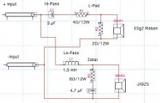
attached is a circuit diagram. if anything is not clear, please ask me to clarify. i believe my previous posts mentioned a 5 and 3 ohm resistor, which i've changed to a 4 and 2 ohm. i like this balance a little better, but it is subtle.
i finished my main cabinets this weekend with solid figured spanish cedar and beech trim on sides and bird's eye maple veneer on the front and top. it looks really good. the cabinet for the ribbon is one i've shown in an earlier post. i'll post a picture in the next few days.
regards, robert
Attachments
This is very interesting to me. I jsut got a pair of JX-92's a couple weeks ago, and I'm planning to do a transmission line bass module with them. I'll be crossing over to a 6" x 12" electrostatic panel. I'm not sure where I'll cross over, but I'm guessing that it will be in the 300 Hz region.
If I didn't do the ESL panel, my second choice would be a ribbon or planar driver.
If anybody is interested in my TL design for the JX-92, I can psot a PDF file of my cad drawings. the enclosure is 30" high, by 7 " wide and 10.5" deep. It's heavily bracced as are most all TL's.
I've still got to check out Martin's mathcad TL design tools.
Sheldon
stokessd said:I've still got to check out Martin's mathcad TL design tools.
I feel a version II coming

dave
Robert
I really can't understand how you manage to get a flat amplitude and impedance with this crossover. I have simulated, built and listened your configuration, and measured again. It sounds as it’s simulates and measures - no midrange. I know, at first I said that it lacks some midrange glove but after much more listening and measuring, I tend towards my latter impression. As we use different baffles - yours has narrow baffle for woofer and no baffle for tweeter, mine is 1.2 x 1.2 inch square (I know - theoretically the worst shape for diffraction but I had my own cosmetic reasons for this particular shape) one can expect some disparity but not so big as I can see now. I am still in opinion that baffle size does change the response of individual drivers and summed frequency response largely, especially if you compare a tweeter with no supporting baffle with tweeter mounted in wide baffle. But even when all this is taken into account one could not end up with such big differences in response graphs. I am not here to say that you have somewhat inferior design - if you like the sound of it, you owe yourself to be happy and keep it like that, especially considering the effort and time you have put into it, to get this result finally. I have tried numerous different crossovers with these drivers and I am still to come for one of my liking. When you first reported that you have come to saticfacory result with this relatively exotic design I was more than happy that finally somebody has succeeded where I had failed. But at the moment I am puzzled and trying to figure out, can we perhaps change some individual driver and summed frequency response graphs in order to find out the reason for that disparity of results.
Regards
Argo
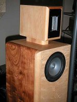
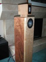
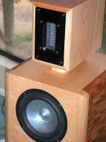
Here are a few images of the completed cabinets (bases made of maple or beech are not yet done).
argo,
I simulated nothing. Not enough data for the acoustic/dispersion/phase shift/mechanical/electrical is known of each and every driver to permit extrapolation to listening responses. I believe speaker simulations are garbage.
All measures were done with completed main cabinet using the software I've previously described. I have one interesting control, as I've mentioned but did not elaborate upon. I also measured my Quad 988 before I sold them. The response curves as similar to what I've seen published in magazine reviews. Therefore, applying some logic, if the Quads are measured accurately--comparable to published reports, using my setup--then using the same set-up should measure the Jordan-ESg2 accurately. Do you have any such validation that your set-up is accurate? Additionally, besides impulse testing for response and impedance curves, I used warble tone testing to confirm frequency response. Both tests agreed very well with one another.
Furthermore, listening tests with many listeners, not just myself, confirmed the similarity in tonality between the Quad 988 and the Jordan-ESg2. No midrange is lacking. I have no clue as to why your differences exist.
Regards, Robert
Attachments
very very nice finishing for the cabinet.
what about jordan's tweeter? did you try it? (before using the esg's) i knew that you tried the neo3pdr!
because refering to mr. Jordan that with the JX92S and Jx53 there will be an overlapping with the midrange, and he said that this is suitable for 1st order XO!
is it true? will it be easier to XOed it in 1st order if there were a wide overlapping?
Gabe,
I had Ronnie at Caroline Audio make a pair with no radius corners and had him only paint the rear and the support stand black. The are his stock JLM design as far as the TL construction goes.
I then veneered the front and top with bird's eye, and put solid wood on the sides (3/4" thick) to further dampen the cabinets. This is the first time I ever veneered anything. I was surprised by the price. The local exotic lumber yard sells a minimum size of 2x4 feet of veneer. The bird's eye cost 12.xx per sq ft, meaning the 2x4 sheet was about $100! 30% was waste and wasn't used as I wanted both speakers to be mirror images of one another.
Inside I lined the upper chamber and rear-most panel down to the input terminals with 40# felt.
regards, robert
Robert,
Let me first congratulate you, those cabinets looks gorgeous.
I simulate everything. I believe simulations gives you a good outlook what the summed frequency, phase, impedance, group delay, polar and diffraction pattern, etc. responses will look like when different crossover frequencies and topologies and driver offsets are used. Though simulations relay on accuracy of individual driver measurements.
Different measurement techniques, hardware/software and environments each have their own limitations off course. Knowing these limitations one can determine how much he can relay upon them. Those limiting factors are all well known and sorted out so basically the output can be interpreted quite certain within these limitations. Modern acoustic simulation software has proved to be as accurate as actual measurements (except THD simulation). Many professionals and hobbyist using these techniques have proved the simulated response to correspond within 0,5dB accuracy compared to actual measurements.
Now, what I am not saying is, that every flat and smooth summed frequency plot should sound the same and equally good to your ears - quite opposite. You have well founded it out yourself and I totally agree with you. Same with the amps, DACs etc. – excellent measurement data doesn’t guarantee a comparable good sound as well in all cases.
What I am trying to say, is that with the individual driver response curves, measurement and simulating systems at my possession (having confidence in their accuracy) I can’t get the same results as you did - that is flat frequency and impedance curves.
This is what I got with your crossover. Ignore the response below 400Hz
Regards
Argo
An externally hosted image should be here but it was not working when we last tested it.
argo,
Thanks for the compliments.
I definitely did not get anything remotely looking like your simulated plots on my measurements (even before adding a zobel). There was no impedance peak at 2K. The plot was flat. (I cannot easily show plots as I work on Macs and my speaker testing is done on a Windows laptop; if I ever have almost nothing to do, I'll work on transfering them.)
When I did the zobel to lower the rising impedance of the Jordan JX92S, it was running alone in the TL cabinet. I fine-tuned the zobel using only the Jordan. Next, I added in the ribbon and worked out the x/o. After this, I re-ran the impedance plot and found the Jordan-ribbon to be flat as described. The ribbon is a flat impedance (purely resistive). Do you account for this in your simulation?
In fact, did you use a JX92S and an ESg2, or did you substitute other drivers when you actually built the speakers? How exactly was your cabinet constructed?
Along those same lines, I tested not only Carolina Audio's JLM cabinet, but also the smaller satellite transmission line, the JSM. It gave the same results as the larger one. The JSM is slightly wider and much shorter, but has roughly the same TL load. I measured both JLM pairs, so this makes 3 speakers that had all exactly the same frequency response, impulse response and impedance plots. This is not too surprising considering the drivers and x/o were identical; only the cabinets varied.
I find it difficult to believe that a generic simulation package can accurately mimic all drivers based on a few parameters. (I cannot speak for him, but I believe Mr. Jordan doesn't put much stock into Thiel-Small parameters for his drivers. He uses a rather different surround loading than most speakers; see his web site for a description.)
Using a generic driver in simulation is a bit like saying any transistor can be plugged in for another: they're all transistors after all. Your simulation plot is nothing like my reality. (It's like someone looking at their instruments in an airplane and saying we cannot be going down, the instruments say we're flying just fine as the ground looms in front of their cockpit.) Simulations are a starting point. All final results (x/o, impedance, time alignment) must be worked out on a functioning prototype. I don't believe any manufacturer would put onto the market an audio product that was only simulated and not refined through prototyping.
These speakers measure fine and sound fine. As I said in an earlier reply, do you have any measurement system (not simulation packages) that you've used to measure commercially produced speakers, and confirmed these results with published accounts? If you've only measured self-constructed speakers, how do you know for sure that your results are accurate? If you cannot say yes to having a commercially produced control, then I would suspect your measurements or how you constructed the speakers.
Again, I have an internal control of my measurement using the Quad 988 speakers. These were used to double check my measurements and to compare while listening. (While this is not absolutely germain to this discussion, I used to own a speaker company, which produced and imported speakers into the US--German Physiks speakers--and for a brief period, Burmester electronics and speakers. I used to meaure many types of speakers and had many opprotunities to confirm my results with the owner of German Physiks.)
regards, robert
rljones said:(I cannot easily show plots as I work on Macs and my speaker testing is done on a Windows laptop; if I ever have almost nothing to do, I'll work on transfering them.)
I might be able to help. I've had to deal with this stuff many times. Send me an email and i can make some suggestions.
dave
Robert,
Let me first apologize on partly quoting your text but I think it makes my comments clearer to follow for others that may have not followed our discussion all along.
Plot displayed in my previous post is indeed a simulation not measurement but the measurement didn’t look very much different. Unfortunately I missed to save the measurement file when I did it so I need to make your crossover and according measurements again and will post the results.
The current simulation displayed does not use generic driver models but actual measured amplitude and impedance responses of JX92S and Esg
MLS method is the primary measurement method of such measurement systems as MLSSA, Clio, Imp Liberty Audiosuite etc.
I have measured some commercially made speakers as well different individual drivers and these measurements correlate very well with manufacturers published graphs.
But I am starting to see a possible reason for disparities of our measurements. Putting aside the front baffle shape and size, a more important criteria is location of the design axis relative to the drivers and the distance of measurement microphone from drivers. I kind of blindly assumed that your design axis is at tweeter's center level and 1 meter afar. That’s where my measurements and simulations were done. BUT, moving a design axis will change the response received by microphone. JX92S has very poor off axis radiation behavior at higher frequencies and especially Esg2, as any ribbon transducer, has a bad vertical dispersion also.
So while two actual individual drivers must have some physical separation witch means you have two separate acoustic centers on vertical axis, the design axis can be chosen anywhere between those two driver centers. Moving a mic vertically closer to one driver center affects the received response by mic of the other driver because the drivers dispersion pattern .
As you have quite tall cabinets and tweeter seems to be higher than your ear level when siting, I tend to believe that you your mic was placed on vertical axis at the same level as woofer’s center. The result would be that at this height Jordan has more high frequency level, while tweeter looses some from higer frequencies and achieved summed response will be more falt. I don’t know I need to check this how much flatter response I can get.
That’s very interesting. May be you can share more about your ex company, if not in this thread maybe in Introductions.
Well simulations, measurements and flat amplitude responses aside I have came to impression, that JX92S doesn’t like very much to be interfered with crossover parts which are excessively trying to attenuate his response very early in frequency band. In fact it seems it mostly enjoys no attenuation at all. Of course adding a tweeter into this kind of slender woofer rolloff will cause problems in higher frequencies because of comb filtering. Things get even worst if you also want to preserve ribbons lovely midrange by crossing it real low. That’s why I have had hard time to mate an Esg to jordan because they both sound best when ran wide and free.
Another point I must state. You said, that you have found in your listening tests, that most music can sound good with most x/o variations but it was only a few x/o variations that could be tolerated with virtually all styles of music. Solo voices, and solo instruments sounded good but groups and orchestras sounded too bright and not airy when woofer was crossed too high. When I evaluate any stereo equipment, my first concern is, how this certain equipment reproduces individual voices and instruments, how natural and free they sound. When the entire presentation of ensemble or orchestra sounds almost flawless but individual instruments or voice loose their resplendence, this part of equipment never finds my favor. On the other hand there are plenty of recordings with different styles of music where big ensembles and orchestras will never sound right on any equipment because of recording and mixing shortcomings. So I guess we have different preferences as well.
cheers,
Argo
Let me first apologize on partly quoting your text but I think it makes my comments clearer to follow for others that may have not followed our discussion all along.
Actually I measured the impedance of ribbon.rljones said:argo,
When I did the zobel to lower the rising impedance of the Jordan JX92S, it was running alone in the TL cabinet. I fine-tuned the zobel using only the Jordan. Next, I added in the ribbon and worked out the x/o. After this, I re-ran the impedance plot and found the Jordan-ribbon to be flat as described. The ribbon is a flat impedance (purely resistive). Do you account for this in your simulation?
Yes I used a JX92S and EGg2. The cabinet for Jordan is 3liters sealed 38W X 26H cm and the tweeter sits on top of that having a baffle as wide as woofer and height as much as tweeter faceplate. This all together forms a square shape baffle 38 X 38 cm (about 1.25 X 1.25 inch). The front side of the box is 1 to 2 inches MDF and back is made from molded aluminium box (lined heavily with acoustic damping sheets). Total depth of the cabinet is 4 inch. Primary intention for such strange shaped cabinet is to have a speakers intended for on wall/in wall mounting with the option to install them also on stands for free field. For free field the speaker will incorporate a switch to change the crossover to compensate a baffle diffraction effect. There is nothing fancy to show you at the moment because it just has raw MDF finish, no grill and no paint or wood veneer on it. Only things what can possible please ones eye are the shimmering aluminum drivers. I kind of like the uncovered finish of both Jordan and Esg, so the grill might never find his place on finished cabinets. At the moment I don’t have a digital camera either to take pictures of the cabinets. When I am finished with the cabinets I’ll try to take some pictures.
In fact, did you use a JX92S and an ESg2, or did you substitute other drivers when you actually built the speakers? How exactly was your cabinet constructed?
We are not talking about making simulations based on Thiel-Small parameters but on measured individual driver amplitude and impedance measurements, are we?I find it difficult to believe that a generic simulation package can accurately mimic all drivers based on a few parameters. (I cannot speak for him, but I believe Mr. Jordan doesn't put much stock into Thiel-Small parameters for his drivers. He uses a rather different surround loading than most speakers; see his web site for a description.)
Plot displayed in my previous post is indeed a simulation not measurement but the measurement didn’t look very much different. Unfortunately I missed to save the measurement file when I did it so I need to make your crossover and according measurements again and will post the results.
The current simulation displayed does not use generic driver models but actual measured amplitude and impedance responses of JX92S and Esg
I am 100% agree with you on this.
Using a generic driver in simulation is a bit like saying any transistor can be plugged in for another: they're all transistors after all. Your simulation plot is nothing like my reality. (It's like someone looking at their instruments in an airplane and saying we cannot be going down, the instruments say we're flying just fine as the ground looms in front of their cockpit.) Simulations are a starting point. All final results (x/o, impedance, time alignment) must be worked out on a functioning prototype. I don't believe any manufacturer would put onto the market an audio product that was only simulated and not refined through prototyping.
I have a measurement system called LspLab and I use a lot my friend's LspCAD’s JustMLS package as well. Both these systems use MLS (Maximum Length Sequence) signal to measure frequency and time response and impedance. LspLab additionally does measurement of the frequency response with discrete sinewave bursts and with a logarithmic sine sweep.
These speakers measure fine and sound fine. As I said in an earlier reply, do you have any measurement system (not simulation packages) that you've used to measure commercially produced speakers, and confirmed these results with published accounts? If you've only measured self-constructed speakers, how do you know for sure that your results are accurate? If you cannot say yes to having a commercially produced control, then I would suspect your measurements or how you constructed the speakers.
MLS method is the primary measurement method of such measurement systems as MLSSA, Clio, Imp Liberty Audiosuite etc.
I have measured some commercially made speakers as well different individual drivers and these measurements correlate very well with manufacturers published graphs.
But I am starting to see a possible reason for disparities of our measurements. Putting aside the front baffle shape and size, a more important criteria is location of the design axis relative to the drivers and the distance of measurement microphone from drivers. I kind of blindly assumed that your design axis is at tweeter's center level and 1 meter afar. That’s where my measurements and simulations were done. BUT, moving a design axis will change the response received by microphone. JX92S has very poor off axis radiation behavior at higher frequencies and especially Esg2, as any ribbon transducer, has a bad vertical dispersion also.
So while two actual individual drivers must have some physical separation witch means you have two separate acoustic centers on vertical axis, the design axis can be chosen anywhere between those two driver centers. Moving a mic vertically closer to one driver center affects the received response by mic of the other driver because the drivers dispersion pattern .
As you have quite tall cabinets and tweeter seems to be higher than your ear level when siting, I tend to believe that you your mic was placed on vertical axis at the same level as woofer’s center. The result would be that at this height Jordan has more high frequency level, while tweeter looses some from higer frequencies and achieved summed response will be more falt. I don’t know I need to check this how much flatter response I can get.
Again, I have an internal control of my measurement using the Quad 988 speakers. These were used to double check my measurements and to compare while listening. (While this is not absolutely germain to this discussion, I used to own a speaker company, which produced and imported speakers into the US--German Physiks speakers--and for a brief period, Burmester electronics and speakers. I used to meaure many types of speakers and had many opprotunities to confirm my results with the owner of German Physiks.)
regards, robert
That’s very interesting. May be you can share more about your ex company, if not in this thread maybe in Introductions.
Well simulations, measurements and flat amplitude responses aside I have came to impression, that JX92S doesn’t like very much to be interfered with crossover parts which are excessively trying to attenuate his response very early in frequency band. In fact it seems it mostly enjoys no attenuation at all. Of course adding a tweeter into this kind of slender woofer rolloff will cause problems in higher frequencies because of comb filtering. Things get even worst if you also want to preserve ribbons lovely midrange by crossing it real low. That’s why I have had hard time to mate an Esg to jordan because they both sound best when ran wide and free.
Another point I must state. You said, that you have found in your listening tests, that most music can sound good with most x/o variations but it was only a few x/o variations that could be tolerated with virtually all styles of music. Solo voices, and solo instruments sounded good but groups and orchestras sounded too bright and not airy when woofer was crossed too high. When I evaluate any stereo equipment, my first concern is, how this certain equipment reproduces individual voices and instruments, how natural and free they sound. When the entire presentation of ensemble or orchestra sounds almost flawless but individual instruments or voice loose their resplendence, this part of equipment never finds my favor. On the other hand there are plenty of recordings with different styles of music where big ensembles and orchestras will never sound right on any equipment because of recording and mixing shortcomings. So I guess we have different preferences as well.
cheers,
Argo
possible explanation for discrepancy
Argo,
I think I can explain the lack in midrange you are getting. Baffle step compensation in the design under discussion is achieved by creating a bit of a gap in the crossover responses and then raising the drive level going to the woofer. This provides the baffle step compensation and eliminates the midrange dip. You may try this in your simulation, but of course your in-wall application is not compatible with baffle step compensation (it doesn't need any).
Can't explain your very pronounced impedance peak. I get about a 15 ohm peak at about 2k (assuming resistive load for the tweeter, this is theory only).
Hope this helps,
Dgoudey
They are still every bit as good. I've made more and have a 5-channel + sub surround with them, using a smaller bookshelf size TM for the center and placing the ribbon on the short edge rather than the top.
Imaging is still incredible, especially after upgrading amps and pre-amps. Every electronic change was easily detectable.
This past weekend a friend who is intereseted in getting them (his wife wants smaller speakers for their home) brought over his Martin-Logan Aerius for comparison. We ran the front two speakers against the M-L. The M-L had a sweeter top we seemingly more detail (a little bright in my opinion; remember from earlier posts that the J92-ESg2 were designed against Quads). The imaging was better with the J92-ESg2. The soundstage was huge and no small sweet-spot evidence as with the M-L.
Verdict: he is selling the M-L and making a pair of Jordan-ESg2s. (Ronnie will build the speakers and I'll fabricate the ribbon housing for him). If you build them, you will not be disappointed.
Regards, Robert
- Status
- This old topic is closed. If you want to reopen this topic, contact a moderator using the "Report Post" button.
- Home
- Loudspeakers
- Multi-Way
- Jordan 92S TL + ESg2 ribbon