James, yes they could be good candidates at first sight, I must look further…
Btw, John could you enlighten us some more on the pros and cons of lateral vs. vertical mosfets, please.
Patrick, Georges, I put myself sometimes about the same questions as you, and it’s why this circuit represented a way to learn, unfortunately John cannot speak too much about it, at least in detail, which is comprehensible, and moreover it’s normal that he doesn’t comment on a circuit which is not his design.
Looking at the K170/J74 vs. K216/J79 datasheets I would prefer to use 1 mosfet rather than 3 or 4 fets (look at Yfs, Ciss, Crss, Vds vs. Id, and linearity at 30/50 mA) for me they look quite good , and I think that noise is not an issue at line level.
However it is true that “drain or collector” outputs appear to give bests listening results as it seems that the action of the load (cable, following input stage) influence more the behaviour of the device configured in follower mode (source/emitter output), by a better circuit isolation to the external world (especially true with fet/mosfets).
Erno Borbely turned around all these configurations, John Curl too, and I suppose that for a mixed configuration both asymmetrical/symmetrical inputs and outputs, with some gain, the Blowtorch undoubtedly represent one of the best achievements to date.
Justcallmedad said:...moreover it’s normal that he doesn’t comment on a circuit which is not his design.
Oups, I mean the circuit I drew in a previous post!
Ricardo,
> However it is true that “drain or collector” outputs appear to give bests listening results as it seems that the action of the load (cable, following input stage) influence more the behaviour of the device configured in follower mode (source/emitter output), by a better circuit isolation to the external world (especially true with fet/mosfets).
How about doing the same as Borbely, i.e. use a complementary follower (originally from John Curl) to drive resistor-terminated, impedance-matched cables (say Beldon 89207, 100ohm, same as Neutrik XLR 3 pin connectors)?
Imagine Borbely's line amp without feedback but with larger values of source resistor.
Patrick
PS Thinking again, ZVN3310 is no good substitute. Though it has similar characterisitcs and transconductance, it cannot dissipate much heat. So one cannot bias it at the linear region, say 150mA.
So we are still stucked with the Hitachi FETs.
Linear operating region for mosfets
I do not see many designs where the mosfets are running in the "linear" region. Even the really hot running pres seem to push IRF610'S AND IRF9610's to the 50 - 80 ma range. The 1 amp range is normally where is see IRF240's and 9240's operating at.
My experiance has been that oversized outputs sound better. Even if operating in a region where the currents are way below rated max.
The 2SK216/2SJ79 are neat looking devices though. Hate to drop 80.00 on ordering a bunch to allow matching up here. But could see where they could be used in many other applications.
I too hope JC chimes in on the relative merits of lateral vs vertical mosfets. One area where the lateral may be lacking is actual matching between N and P channel mosfets. I think the newer IRF verticals have better P channel devices than older parts. The P channels are a weakness once you refine your circuits to the level of the BT, Pass, or Lyra. The distortions and unlinear response are primary flaws once power supply, layout, and operating parameters are optimized.
In my system, the current flow is several levels of magnitude under you calculations. 1 volt into 100K, so 10 ua should get it to 100 dB speaker output. Even with capacitance charging and cabling I suspect 1 ma is more than ever outputted. But I have found using devices rated for a amp or more sounds faster and louder than using devices with a couple hundred ma rating. Just another mystery. A single 2K170V/2SJ74V pair should be plenty. But I know better to even try, it will be seriosly lacking.
I suspect the negitive temp coefficient of mosfets has something to do with this. When higher voltages hit the gate, this heats a little bit of the cmos and reduces the gain. With larger devices the effect is minimized.
Even for a preamp, the 510/9510 sounds better than the 610/9610 to my ears. In fact sounds real good overall. But I have never heard the Hitachi laterals, they may be way better still.
George
Folks, I guess I should input, just to show that I am still here at least. ")
I feel that it is easier to use a mosfet for the output devices. This is because they have inherently higher voltage breakdown, and can be found in some sort of 'power' package. J-fets could be made this way, but they are not normally available, except in smaller packages.
I have used the Hitachi 213-16, J76-79, for many years. The P channel devices, unfortunately, are more like triodes than normal fets. This will add a lot of second harmonic distortion to a typical balanced circuit. Still, they are pretty good, if you watch out for this.
In general, I have found it better to make simple, balanced circuits, rather than complex circuits with multiple junctions in the thru-path. That is why I use such a simple circuit, rather than add followers, etc. It depends on what you are trying to do. If you need high voltage gain, then adding a follower can give you all the gain that you usually need. However, if you only need a gain of 10 or less, open loop, then adding a follower stage will be redundant, unless you need really low output impedance or to drive very long cables.
While I used a design technique that I originally found in Charles Hansen's design, I am really trying to parallel (in solid state) the successful tube output stage, first set forth by Audible Illusions. I worked with Audible Illusions for a few years, part time, and fell in love with their open loop tube output stage. I tested it more fully, as well as listened to it at home, and decided that it was a 'winner'. My contribution to the 'Blowtorch' preamp was to make a fet version that could behave well open loop, with a minimum of distortion. Instead, of a single tube, I had use a complementary differential folded cascode. Quite a trade-off, but I did get to eliminate the output coupling caps, and get balanced output drive. The measured results are similar.
john curl said:I am not saying that the Hitachi devices would not work in this case, but to understand that they are prone to output impedance mismatch, in general, and this could be a problem in some designs. Some of the Toshiba 1A parts look very interesting.
This is not totally clear for me John, could you explain further ”output impedance mismatch”, eventually with a critical example case, please.
All solid state devices have a finite output impedance when biased in the linear region.
We often compare the different output impedances to triodes to pentodes, or somewhere in between. If you look at Hitacihi lateral 1/2A mosfets on a semiconductor curve tracer, you find that the output curve of the Hitachi P channel looks like a triode, and the Hitachi N channel looks like a pentode. If both were 'triodes', then there would be a better match, alternatively, if both were 'pentodes' there would be a better match.
Since the output impedances are not matched, it is difficult to use these devices directly, in push-pull, as gain stages. However, they will work fairly well as a cascode, since the output impedance will be much increased, just because the device is operating as common gate, rather than common source. Then the mismatch may still be measurable, but within reasonable limits to be useful.
Hit. vs. Tosh.
Yes, thanks John, now I can see these curves not identical also on Hit. data sheet. Toshiba 2sk2013/2sj313 are much better. But are they still better choice considering much greater junction capacitances?
john curl said:If you look at Hitacihi lateral 1/2A mosfets on a semiconductor curve tracer, you find that the output curve of the Hitachi P channel looks like a triode, and the Hitachi N channel looks like a pentode. If both were 'triodes', then there would be a better match, alternatively, if both were 'pentodes' there would be a better match.
Yes, thanks John, now I can see these curves not identical also on Hit. data sheet. Toshiba 2sk2013/2sj313 are much better. But are they still better choice considering much greater junction capacitances?
john curl said:...We often compare the different output impedances to triodes to pentodes, or somewhere in between...
Ohhh yes!!! I have in mind linearity and changes in Id vs. Vds, but not in terms of output impedance mismatches between complementary pairs and of higher impedance modulation for “triode” Mosfets!
The solution would be to cascode the folded cascode, but as you pointed out in an earlier post, not sure that it will be worthwhile in a “line level” folded cascode.
Would you do it in a folded cascode power amp driver or pre driver stage (higher swing)? Even with best suited and matched devices for this purpose, like the Toshiba ones?
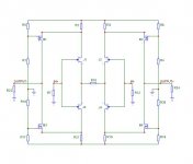
Lumanauw, the connection you mention in Charles' schematic has no effects with AC (1MegOhm resistor and 1µ cap), it's DC feedback. If you do not have DC offset issues, I would leave it out.lumanauw said:Hi, Courage,
Is there any benefit if R1/R18 junction is connected to -output (not to ground) and R4/R20 junction is connected to +output (not to ground) like Charles Hansen's?
Tino
- Status
- Not open for further replies.
- Home
- Amplifiers
- Solid State
- John Curl's Blowtorch preamplifier