PMA said:You guys should reconsider what you are trying to discuss. Cable termination is of no importance for audio signals, it is important only for EMI induced voltages or fast D/A residuals in audio. BNC or F-SMA are great, but again, we do not speak about 2GHz signals. The weakest point of RCA-CINCH is its construction, and the fact that it connects live earlier than ground wire, this results in SDI potential damage.
Pavel, I was talking about digital interconnects. Anyway, WBT makes RCAs that, when connecting, connect first the sleeve, then tip, and the reverse when disconnecting. Can be connected/disconnected with live equipment.
Jan Didden
Bob Cordell said:
Hi Bonsai,
I'm sorry if my post created so much confusion. I'll try and clarify it and complete the thought.
When I mentioned the 49.9 ohm series resistor at the RCA followed by a shunt 100 pF, I was thinking as the amplifier designer who wants to build his amplifier to be as best-performing with whatever unknown source and interconnect the user employs.
The 49.9 ohms and 100 pF is just the first line of input EMI ingress defense, right at the connector. It properly terminates the interconnect with the best compromise at very high frequencies without placing an undue capacitive load on the preamp that is driving it. A 100 pF directly across the input would not be as desirable because it would mis-match the interconnect at very high frequencies and possibly cause resonances. The 49.9 ohm resistor in that regard provides good damping.
When the input lead gets to the circuit board, there is additional lowpass filtering of the kind ordinarily found at the input of an amplifier, usually one or two poles, and perhaps staggered to produce a linear phase rolloff approximation. These LPF sections have higher resistive impedances associated with them. Together, they should have less than perhaps 0.1 dB of attenuation at 20 kHz.
Now let me put my preamp manufacturer hat on. In an earlier post, Edmond stated that he would not feed the output of a preamp to the interconnect without at least some series resistance. I agree with him 100% and always follow this practice. This is an easy way to achieve a series source termination of 50 ohms (the considerations may be a little different for preamps with naturally higher output impedances than 50 ohms, like tube preamps).
So if you follow these practices at both ends, you will have a transmission line that is properly terminated at very high frequencies at both ends if it is 50 ohms. It will always be properly terminated at the source end. Even if the interconnect is not 50 ohms, perhaps 75 ohms, these practices will be quite effective. Transmission lines behave best when they see a resistive termination of some sort at both ends, so there are few oppunities for resonances.
Finally, it is important to think of the loudspeaker cable as a transmission line with a characteristic impedance as well. Ideally, the loudspeaker should present a resistive load at its input terminals out to VHF frequencies to give that transmission line at least some kind of resistive termination, even if the impedance will not be right. There are those who advocate putting a Zobel network at the loudspeaker terminals for this reason. 100 ohms and 0.05 uF in series is not a bad choice. Some loudspeakers that use resistive pads for the tweeters have an input impedance that looks pretty resistive up to quite high frequencies, so they might not benefit as much, but this depends somewhat on their internal wiring.
Cheers,
Bob
Bob,
What exactly does "high frequency" mean in this context? 1MHz? 10MHz? 100MHz? To me, anything that is beyond the unity gain frequency can be safely neglected. Any better definition?
In this view, assuming Fu=5MHz, the wavelength is about 60 meters. Using your own criteria, line effects start at L/6 that is, 10m. Do you think 10m is a realistic length for a home audio environment (I'm not talking about studios here)?
Charles Hansen said:
They are also incorrect. They show a system with matched inputs and outputs having 5 Vp-p at the source and 4 Vp-p at the receiver. Then they show a system with a high impedance receiver with 8 Vp-p at the receiver.
That's a pretty good trick -- a "straight wire with gain", eh?
It is certainly possible for a transmisssion line to produce a larger signal at the receiver than the incident wave. Indeed, with a positive reflection coefficient of 1 the incident wave doubles when it is reflected and adds in phase. It is easy to see values of .8 or .9 in practice. I did not see your post when I posed this question having seen it in practice, it was not exactly this problem but very similar.
Line length comes into play as compared to the rise time of the driving source, and bandwidth of the signal with regard to standing wave resonances. Normal audio is usually well below the regions of concern.
Pete B.
We used to keep an old Craftsman drill around the lab to generate RFI. You just run it right up against your circuit.
In a pinch, a cell phone can be used to induce the "angy bees" RFI noise if cables/equipment are not balanced or shielded properly.
ZAP
chascode said:
One of the toughest tests in the EMI susceptibility test suite we use in aerospace, both MIL-STD-461/462 and RTCA DO-160, is the "buzzing relay" test, and it is one that is easily duplicated without expensive EMI test gear and a screen room.
You wire the normally-closed contact of a 28 vdc relay (we use a Mil-R-6061 relay) in series with its un-supressed coil and energize it. It will "door bell" and produce inductive discharge spikes in the conductors. The spikes are coupled to the input wires of the unit under test by securing the relay wiring to the input wires. This is done using both polarities of the 28 vdc source.
Of course, the abused relay contacts do not last very long in this test. We use a 4PDT relay so we have two sets of contacts to burn out and can extend the test setup test time.
You can also increase the distance between the relay wiring and input wiring to determine the audible and measurable effect on the input circuit.
Best, Chuck Hansen
Great idea, Chuck.
I remember as a tennager we used to do this. We called the device a "discombobulator".
Cheers,
Bob
syn08 said:
Bob,
What exactly does "high frequency" mean in this context? 1MHz? 10MHz? 100MHz? To me, anything that is beyond the unity gain frequency can be safely neglected. Any better definition?
In this view, assuming Fu=5MHz, the wavelength is about 60 meters. Using your own criteria, line effects start at L/6 that is, 10m. Do you think 10m is a realistic length for a home audio environment (I'm not talking about studios here)?
Hi syn08,
In the context of my discussion about far-end termination with 49.9 ohms and 100 pF, "high frequency" is above 30 MHz. That is where the frequency corner is formed by 50 ohms and 100 pF. That is also where the termination begins to look reasonably decent. However, it is important that lower frequencies than 30 MHz be dealt with by other means. Glen has pointed this out in respect to am broadcast transmissions. However, frequencies below 30 MHz are more easily dealt with by conventional lowpass filters at the input of the amplifier. There I like to see some significant input low-pass attenuation beginning at frequencies lower than the closed loop bandwidth of the amplifier.
Cheers,
Bob
")
scott wurcer said:We used to keep an old Craftsman drill around the lab to generate RFI. You just run it right up against your circuit.
What sort of spectrum did it transmit?
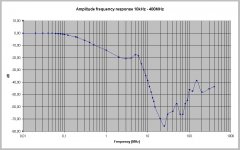
PMA said:Should be stated that HF can bypass RC filters, and spread randomly thru system, depending on construction (wiring) and components parasitic impedances. Example of audio gear measurement:
This is absolutely right, and is the reason why the 49.9 ohm/100 pF combination should be placed right at the RCA jack. The use of a low-inductance capacitor is also important here. A 100 pF COG 0402 surface-mount capacitor would probably be best, but most of the time I use a miniature silver Mica.
Cheers,
Bob
Has anyone sucessfully used ferrite beads in the input of their preamp and can honestly say there was no degradation? I'm asking those who have listened to the best since I usually can't hear things others claim to. The reason I ask is that I have noticed that many of the best microphones make liberal use of RFI stoppers, beads right on the capsule, inductors in the output, etc.
I'm thinking ahead to a project with massively paralleled devices on the input and I want to leave a space for SMD beads in each gate.
I'm thinking ahead to a project with massively paralleled devices on the input and I want to leave a space for SMD beads in each gate.
scott wurcer said:I'm thinking ahead to a project with massively paralleled devices on the input and I want to leave a space for SMD beads in each gate.
I'm sure I'll get lots of people that want to argue with me, but in my experience ferrite causes lots of sonic problems. Do a search for posts by me with the word "ferrite" and you'll find extensive details. I know about this because I learned the hard way. We used ferrite in our products for about two years before we finally realized the sonic problems it created. I would never, ever use ferrite beads again, especially directly in the signal path.
As an aside, I'm not sure why you want to make something with "massively paralleled devices". You still have stock of the discontinued Toshiba parts that are equivalent to a paralleled pair of K170s and J74s. Those parts are of exceedingly low noise, to the point where they will have inaudible noise with any phono cartridge extant.
On the other hand, if you are making some sort of instrumentation device and need ultra-low noise, then by all means go ahead and include ferrite beads. I doubt that they will *measurably* degrade the signal, only audibly.
my experience mirrors Charles' - FB are ng.
at least the one's I've worked with...
_-_-bear
Damien might have something to add here... the Spectral Amps and preamps had bandwith quite a ways into the AM broadcast band... was that found to be an issue in practical terms?
at least the one's I've worked with...
_-_-bear
Damien might have something to add here... the Spectral Amps and preamps had bandwith quite a ways into the AM broadcast band... was that found to be an issue in practical terms?
I found ferrites dissapointing in both EMI rejection and sound. I used them on the Spectral products and didn't get far with them. I have since learned a lot more about how to use them and not use them. I wouldn't use ferrites today on a High Z input. I can now get 3 MHz power bandwidth on a line stage with pretty good immunity without ferrites by careful layout and methodical stability tweaking.
Also you will need something real and low Z on the gate for the ferrite to do anything. A ferrite acts like a resistor at high frequencies, works well for low Z systems (50,75,100 Ohm networks) and introduces losses. But a FET is a sort of cap that changes with many things but is mostly high Z so the losses of the ferrite don't do much. And effective layout almost needs a microwave simulator to make progress.
Also you will need something real and low Z on the gate for the ferrite to do anything. A ferrite acts like a resistor at high frequencies, works well for low Z systems (50,75,100 Ohm networks) and introduces losses. But a FET is a sort of cap that changes with many things but is mostly high Z so the losses of the ferrite don't do much. And effective layout almost needs a microwave simulator to make progress.
You could not measure a microwave transistor like an MRF901 in a Quan-Tech without beads so I guess my experience on their effectivness in preventing parasitic oscillation is different from others.
I'm sure there are many "super-disks" out there that had them right at the mike inputs.
http://recordist.com/ampex/schematics/schoeps/221bschem1.gif
I'm sure there are many "super-disks" out there that had them right at the mike inputs.
http://recordist.com/ampex/schematics/schoeps/221bschem1.gif
- Status
- Not open for further replies.
- Home
- Amplifiers
- Solid State
- John Curl's Blowtorch preamplifier