Bias quantity (current) is the most important factor, but also the optimum current with the respective emitter resistor. Often these amps are starved for quiescent current in order to make the amps run relatively cool. The optimum range is 15-25mV across each and every output device at idle. What about it PMA. What does your test amp measure?
I think I know these amplifier's basics.
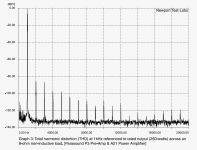
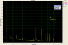
Interestingly, there is a review of the A21 that was published in Australian HiFi Magazine, about 10 years ago, author Steve Holding. They measured at 250W/8ohm and the spectrum is very similar to my 100W/4ohm measurement.
I also have my measurement of 328W/4ohm spectrum, but I am not posting it, as the amp has problems with power supply related intermodulations at such high power.
Attachments
Last edited:
PMA what is the voltage across one of the emitter resistors at idle? This is important! If it is too low, then it should be increased and retested. If it is in the range of 15-25 mV then I would only recommend the A21, (now discontinued by the way) for 6-8 ohm loads.
Last edited:
Thanks Scott.I presented my alternative (even Thorsten L. liked it).
You suggested the shunting to ground input capacitor C1 as a general solution regardless of the particular opamp IC.
George
Attachments
Thanks Scott.
You suggested the shunting to ground input capacitor C1 as a general solution regardless of the particular opamp IC.
George
Each op-amp might have slightly different values depending on their GBW product but the principle works for any of them.
I would like to say, according to my friend who owns a record store in town and has lived here or visited here throughout his longer life than mine...
There's more record stores than ever in town. Even my health food store I stop at sells them. Barnes & Noble has a pretty big section, and stores I've never been in have some too. Maybe it isn't like the 70's, but dead? I don't see any CDs forsale at my health food store...
There's more record stores than ever in town. Even my health food store I stop at sells them. Barnes & Noble has a pretty big section, and stores I've never been in have some too. Maybe it isn't like the 70's, but dead? I don't see any CDs forsale at my health food store...
Hi Robert,
The original thread was started by Darry. I cut the thread twice now to keep the number of posts manageable for the server to deal with. Nothing has anything to do with any quack clock.")
-Chris
What are you talking about?What about the Kwak clock? Elso is the one who started this thread.
The original thread was started by Darry. I cut the thread twice now to keep the number of posts manageable for the server to deal with. Nothing has anything to do with any quack clock.
-Chris
Yes, IIRC Mr. (Dr.?) Small claimed that he gave this idea to Phillips around day one. When I pointed out that the 5534 has a high output impedance at RF and the cap stops working he would have none of it. I presented my alternative (even Thorsten L. liked it).
I'm using a similar trick with the ESS DAC's pretty successfully. With a differential out DAC you can bridge a cap from plus out to minus out on a current out DAC. The ESS dacs clock at up to 100 MHz so its a safe bet that no audio grade opamp will keep up with any glitch energy.
I think I know these amplifier's basics.
Interestingly, there is a review of the A21 that was published in Australian HiFi Magazine, about 10 years ago, author Steve Holding. They measured at 250W/8ohm and the spectrum is very similar to my 100W/4ohm measurement.
I also have my measurement of 328W/4ohm spectrum, but I am not posting it, as the amp has problems with power supply related intermodulations at such high power.
I am surprised at all the harmonics above 2H and 3H. How does that happen? I thought with the use of FETs that should not happen.
THx-RNMarsh
Maybe it isn't like the 70's, but dead? I don't see any CDs forsale at my health food store...
My idea of a record store is like Rose Records was in Chicago, this is dead long dead.
I'm using a similar trick with the ESS DAC's pretty successfully.
When you say 'sucessfully' does that mean you have measured reduced distortion with a particular value cap?
When you say 'sucessfully' does that mean you have measured reduced distortion with a particular value cap?
I'd probably qualify success in this case as not increasing distortion while reducing common-mode high frequency components.
My idea of a record store is like Rose Records was in Chicago, this is dead long dead.
I don't "shop for records at health food store" but I am pointing out there out there, lots of them. I go to several that are only record stores.
Richard, the very hi order distortion is either xover distortion, from underbias, or the residual in the test equipment used at the time. Nothing is perfect, (except my input stage) '-)
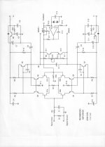
For further discussion, this is the template that I made 26 years ago for Parasound to follow for the less expensive power amps. The A21 follows this template fairly closely.
For further discussion, this is the template that I made 26 years ago for Parasound to follow for the less expensive power amps. The A21 follows this template fairly closely.
Attachments
Last edited:
I'd probably qualify success in this case as not increasing distortion while reducing common-mode high frequency components.
Thinking back I misunderstood, it would do nothing to common-mode signals if it's across the outputs.
If things like clock feedthrough are not differential mode, it might not be very helpful.
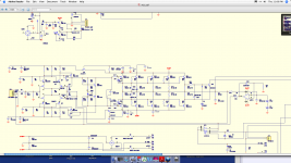
About 10 years ago I built an amplifier, which is in fact based on John Curl's topology. Several pieces were built within 1 year that time and they still work well at their owners.
PA4 power amplifier
I do not have exactly same measurements, from that time, as I have made yesterday on A21, however the old plots show much faster decay of high order distortion components. Yes, it was loaded with 8ohm, but even with 4ohm it was not too different, as I remember. I agree that quiescent current is important, my was about 100mA per pair. 4 pairs, so it was about 0.4A. 0R22 emitter resistors.
The high orders shown that time and yesterday are not measurement residuals, they are just there in the measured subject. Remove load and high orders are gone.
I think that in case of A21 it may be a case of loopgain frequency response. I also posted a THD vs. frequency at 10W yesterday and one can see that the distortion gradually rises with frequency. So there is not enough FB to reduce high order harmonics in the A21, though their origin is in the AB output stage and maybe low quiescent current.
Attachments
Well PMA, we won't know what the distortion is in your measurements, unless you measure across one of the emitter resistors and find at least 15mV. More like 22mV might be more optimum, but I doubt that the heatsink can support it without getting too hot.
However, the Australian measurement, made a decade ago, MIGHT be putting in the extreme hi harmonics from the test equipment residual. If you can offer any suggestions, I would appreciate it. I do realize that the A21's fet driver is starved somewhat, but I tried to change the value and it did not help much.
However, the Australian measurement, made a decade ago, MIGHT be putting in the extreme hi harmonics from the test equipment residual. If you can offer any suggestions, I would appreciate it. I do realize that the A21's fet driver is starved somewhat, but I tried to change the value and it did not help much.
Last edited:
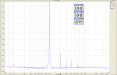
I think you could read from my post that I had 22mV per one Re resistor. I wrote 100mA and 0R22, this makes 22mV . My measuring system had <0.001% distortion, H2 and H3, free from high order distortion. I think this is a nit-picking. You can see a measurement of another amplifier, into 4ohm, free of high order harmonics. It has a 3EF output stage and multi-pole feedback, that is much more effective in distortion reduction. Still not as good as class A. The A21 has high order distortion components when asked to give some power. This may be a result of either underbias, or non-optimal feedback action which is not able to reduce higher harmonics because of decreased loopgain at higher frequencies. This is normal and usual. I do not think that Australian measurements had inherent high order harmonics in the system. It rather sounds like an excuse, to me.
. My measuring system had <0.001% distortion, H2 and H3, free from high order distortion. I think this is a nit-picking. You can see a measurement of another amplifier, into 4ohm, free of high order harmonics. It has a 3EF output stage and multi-pole feedback, that is much more effective in distortion reduction. Still not as good as class A. The A21 has high order distortion components when asked to give some power. This may be a result of either underbias, or non-optimal feedback action which is not able to reduce higher harmonics because of decreased loopgain at higher frequencies. This is normal and usual. I do not think that Australian measurements had inherent high order harmonics in the system. It rather sounds like an excuse, to me.Attachments
I don't "shop for records at health food store" but I am pointing out there out there, lots of them. I go to several that are only record stores.
I apologize, my reference was probably unknown to you. I meant a record store still stocking a nearly complete selection of EMI, Decca, Argo, etc. in shrink wrap at original retail prices.
- Status
- Not open for further replies.
- Home
- Member Areas
- The Lounge
- John Curl's Blowtorch preamplifier part III