What do-you think of this ?
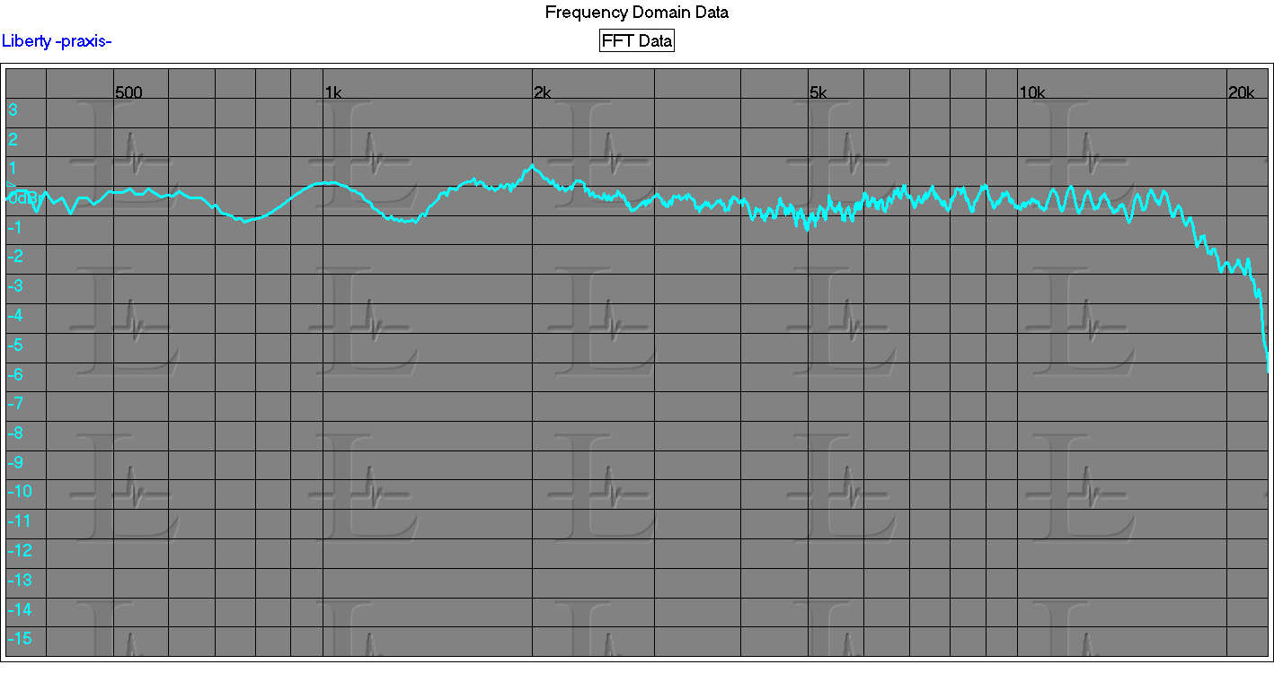
Response curve:
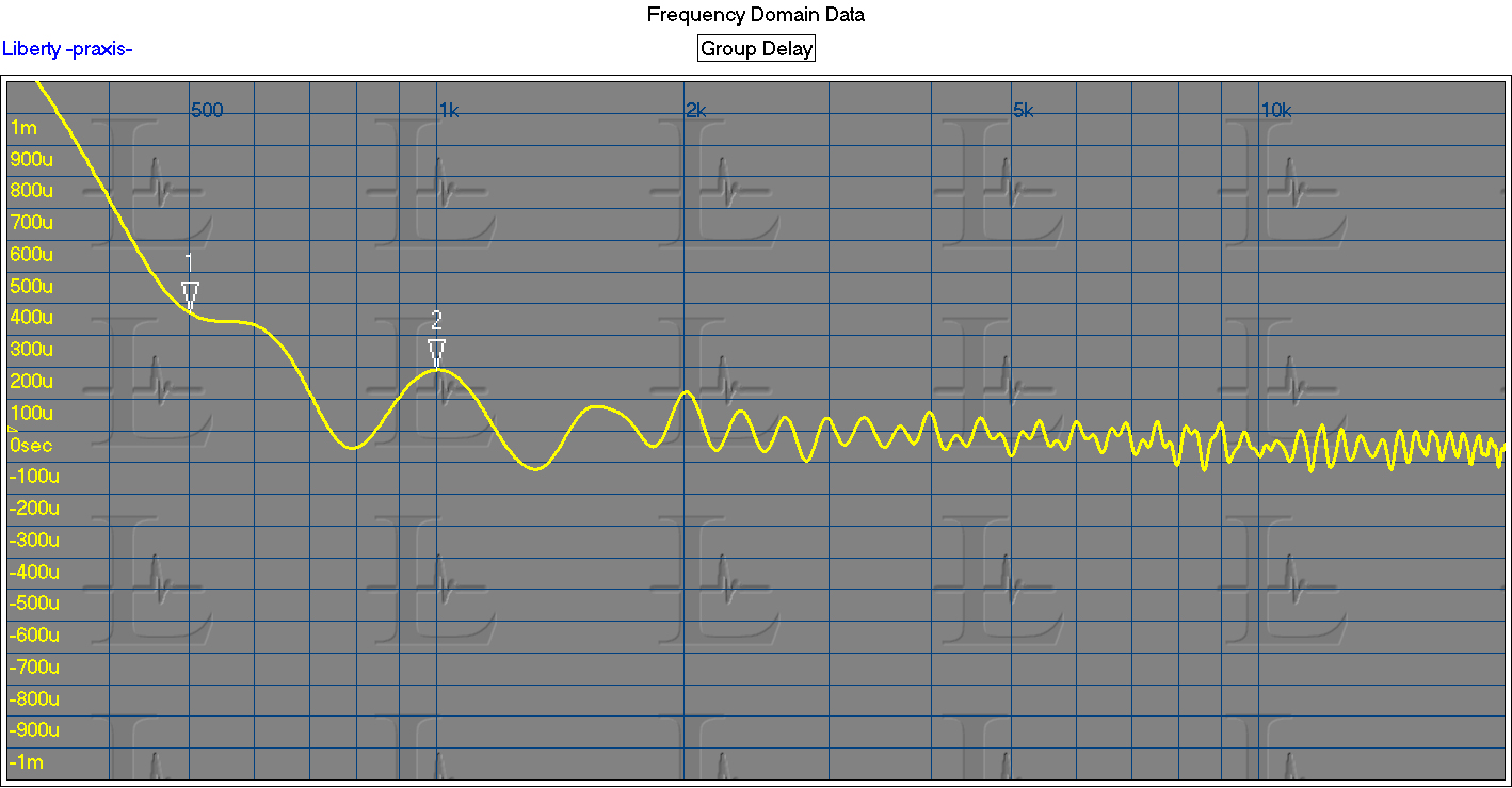
And group delay:

Yes.
THx-RNMarsh
Last edited:
My girlfriend at the time noticed it. I think I didn´t say anything.Not married ?
T, your frequency response curve is great, but your time response curve is marginal.
Richard, your time response is great!
However, here is another (older) JBL that does not look so good:.
Richard, your time response is great!
However, here is another (older) JBL that does not look so good:.
Attachments


VERY Nice.Don't feel bad, T. Look at the time response of my Wilson Sasha speakers:
But don't fool yourself, analysing the one I showed. Those enclosures use a digital active filter with DSP.
You know:

(Why feeling bad, they are not mine ;-)
Last edited:
Actually, I do have a small single layer from a double layer paper towel partially diffusing each HF driver. They hang from the top a bit in front of all but the lower 1/4th or so of each driver, and there is a thin vertical slit in the middle running up about half-way exposing a bit more of directly radiated sound. Adjusted to taste, and doesn't sound bad. With the subs, the frequency response is decent but not tweaked perfectly flat. Percussion instruments produce tight impulses and cymbals sound pretty real. Of course, it doesn't hurt that the old Bryston 4B was recently retired and replaced with an AHB2.
EDIT: They are NS-10M to be precise. Sorry if any confusion.
The toilet paper does not diffuse, but its reflection back to the driver destructively interferes with some frequencies, diminishing the shrillness a bit.
Vacuphile, my answer was ironicous, but not aggressive. This question is, in fact very simple. Please make an effort to understand what I will try to explain despite my poor poor English that make me feel like doted of the QI of an oyster.
We don't know how to build systems with constant directivity all over the bandwidth. So we will will lost more energy outside of our listening places in low frequencies than in high frequencies where the directivity is reduced. In the same time, the room will add its resonnances (or reflexions) in a way that is not universal, because different in all the listening rooms.
That implies two things. First the global subjective linearity of the bandwidth will differ from one room to another. Depending of this situation you cannot take as granted a omnidirectional speaker will be better than a directional one, even if it will sound more linear in your room witch is a specific and particular situation.
YOU have to linearize you systems frequency responses in your rooms before to compare the two solutions.
I can only testify that when people listen to my system, very directive, because horns, the always say a word about how precise and near magical is the localisation. My response curve, in free field, is slowly descending all along the bandwidth, only way to get a near good linearity at the listening point in most of the rooms with a minimum of acoustic treatment.
For me, (and i was designing omnidirectional speakers for the company I was working for, long time ago, just for money), omni is just like a bad bad response to the problem, like make all the population of the world hill of a disease because you you have a climate that is the best to survive with this disease, and pretend you have the best wealth system. The ideal system is a system with a directivity constant all over the bandwidth that reduce the reflexions outside of the listening area to a minimum. An elementary logic.
Well, I just find a way to image my purpose. Omni directional speakers use the same solution than painting in black the walls of a room with a lot of smokers inside, to minimize the speed the walls turn in yellow with white walls.
Or to treat someone with a flame thrower to let-him no longer suffer from mosquito bites.
I think speaker directivity is one of the areas where there's no "correct" answer in hifi (whereas there are no arguments to be made for vinyl over digital for example, and I also struggle to see any arguments for using passive over DSP-based crossovers these days).
I like both narrow and wide-to-omni directivity. I find that narrow and omni directivity do different things psychoacoustically with me as a listener. Narrow directivity (or listening in the extreme near-field) gives me a sense of seeing into a different room altogether. This can be quite cool, but it remains a slightly artificial experience for me. My brain ain't buying the illusion, kind of. Omni directivity gives me a feeling that the musicians are playing in my own room - or rather, it fuses my own room with the room I'm looking into. I personally find this to generate a much more convincing illusion, particularly on acoustic material.
In the end I realized that my preferences were a bit schizophrenic. I prefer omnis for classical and quite a lot acoustic jazz etc. While I prefer narrow directivity and/or nearfield listening away from walls for modern studio music, where the stereo image is constructed and artificial in any case. So I decided on having two systems, omnis for the living room, and more directional speakers for near-field listening in the man cave.
Yes, this is a very good description of the difference between "I am there" and "They are here" I use dipoles which could be considered half way between the two extremes but they definitely give me the "they are here" experience which for the reasons you suggest, I find comfortableI find that narrow and omni directivity do different things psychoacoustically with me as a listener. Narrow directivity (or listening in the extreme near-field) gives me a sense of seeing into a different room altogether. This can be quite cool, but it remains a slightly artificial experience for me. My brain ain't buying the illusion, kind of. Omni directivity gives me a feeling that the musicians are playing in my own room - or rather, it fuses my own room with the room I'm looking into. I personally find this to generate a much more convincing illusion, particularly on acoustic material.

. I personally find this to generate a much more convincing illusion, particularly on acoustic material.
.
I think this is the nail on the head. It's an illusion. Two speakers cannot generate a soundfield that replicates being there. I think the idea of seperate optimisations for studio and real acoustic music does make sense from creating the wanted effect for happy listening.
I reckon this is not seen to often, this is 700 Hertz and an actual measurement:
What is interesting, the Tweeter is in reverse phase - work that one out.
Now move the microphone 4 inches and see what you get. If the tweeter is in reverse phase, it is likely 2nd order LR xover.
Now move the microphone 4 inches and see what you get. If the tweeter is in reverse phase, it is likely 2nd order LR xover.
Not really, it's about how they meet up in time, but you are right, this is not Butterworth, where the 'window' is very small:
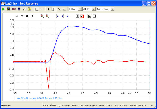
Final Step Response, this one captured at 2 Metres and 15° off axis, but would hold up even at 30° off axis.
The only part of the response that is out of phase is above 16KHz with 4 Watt input, and with 1 Watt input is 22KHz.
The end result:
Vector summing below those frequencies, 16-22KHz, is very high, of course 100% would be ideal and for the most part is right up there, this means excellent off axis response and a wide 'window' - so feel free to move around.
PS: Makes a mockery of the idea of finding acoustic centres in drivers, but time does not lie.
Last edited:
I was able to get midrange freq area to produce a square wave -- at the cross-over freq. Back before there were PC's and DSP. All analog.
I designed and built a opamp based cross over which I could continuously vary the slope and freq. I still have it in storage. I could get a perfect time and phase match between drivers. One driver (Mid-High) I was able to move forward and backward. Between moving it and adjusting the slope (phase), I could get a nice square wave. The mid-hi was a JBL LE175DLH (no longer made) that had a 90 degree spherical dispersion lens on the horn.
Now we have DSP and waveguides and powerful processing tools. But the fundamentals of what you have to get for accurate results has not changed.
You can have your cake and eat it also.
THx-RNMarsh
Last edited:
This mailshot just hit my inbox:
NX1000 | Portable | Power Amplifiers | Behringer | Categories | MUSIC Tribe
"...With SmartSense Loudspeaker Impedance Compensation"
Hmm...
NX1000 | Portable | Power Amplifiers | Behringer | Categories | MUSIC Tribe
"...With SmartSense Loudspeaker Impedance Compensation"
Hmm...
Who teaches anything different these days (I don't care what the wiki says)? In high school maybe to give people a basic understanding of electronics. Dan's view is what I learned the voltage and current are measurable against accepted international standards the incremental resistance is what's left. You calculate the integral of the power in the resistance because (save for radiation) that is where the energy is lost as heat or real power delivered.
You can fool old school power meters, even make them run backwards, but that's their problem not the physics.
???
R,L & C, (D? anyone?) are basic. Dissipation of energy is not what was under discussion. It was the sag in the peak voltage of an AC power-line system. Yes the source impedance can be reasonably modeled as a voltage in series with a resistance. The load cannot.
In my house I have motors in my washing machine, dryer, freezer, water heater and exhaust fan. Heating elements in the dryer and oven. They are all loads that are intermittent and very low duty cycle. My lights, inductive cook tops and audio video gear are electronic loads that do not draw current over the entire AC voltage cycle. These gizmos have a higher duty cycle. They tend to clip the peak voltage. That is what causes the AC power-line distortion.
The inductance of the motors is often compensated by placing capacitors across the power-line. Usually not done for small motors, but the power company may add them to their lines to improve system efficiency based on actual field measurements.
At my shop we pay more if our power factor results in inefficient use of the AC distribution system.
Just in case someone doesn't understand power factor, many loads are inductive. Typically these are motors that are running under a light load. As an inductor has the voltage across it out of phase with the current through it no power should be dissipated. However as the AC voltage source is located some distance away the current will flow through the connecting wires between source and load. As these wires have resistance they will dissipate power. The technique is to place a capacitor at the inductor to resonate the LC circuit at the power line frequency. Thus the circulating currents will have very short connection wires and less resistance resulting in less power loss.
I did a bit a few years back where I built a switched capacitor bank to resonate an individual wall outlet at the line frequency. It did make an audible difference. BUT you had to switch in the capacitors with the gizmo unplugged as the circulating currents were high enough to weld the switches! The system could be optimized by using a purpose build AC power-line FFT monitor to adjust for minimum harmonic distortion.
Last edited:
Ed, I think we've come so far astray of the original discussion. PFC is definitely an important aspect of power consumption and distribution, but not what precipitated the back and forth. I originally was confused by your use of the term "non-Ohmic" or something to that effect, when you were describing the deleterious effect of rectification and a capacitor load on the power distribution side.
In any case, I'll keep asking for clarification when you call something ohmic or non-ohmic in behavior, because I still don't know when you apply the term. As for myself, I never use ohmic (past the "ohmic contacts" as a snippet of my work experience) as a descriptor, instead describing the resistance and it's behavior in the region of interest if that's germane to the discussion at hand.
In any case, I'll keep asking for clarification when you call something ohmic or non-ohmic in behavior, because I still don't know when you apply the term. As for myself, I never use ohmic (past the "ohmic contacts" as a snippet of my work experience) as a descriptor, instead describing the resistance and it's behavior in the region of interest if that's germane to the discussion at hand.
The toilet paper does not diffuse, but its reflection back to the driver destructively interferes with some frequencies, diminishing the shrillness a bit.
Yes. I slipped a bit of a euphemism in there, but I think you are right. Nonetheless, it was adjusted to taste with some success. I like it better but the speakers may be the next thing to retire. Don't know what to use instead though. Don't want all-in-one speakers with a class D amp inside. Do want sealed enclosures and very tight time-response, yet all around accurate enough for mixing and maybe a little mastering. Don't want to spend a fortune either. Tough set of requirements, more like impossible.
EDIT: It was actually a very thin piece of paper towel, and what happens is probably a little more complicated than only diffusion or only reflection, but it can help if not overdone and tuned a bit.
Last edited:
Hi Mark,
You probably would be best with something that is "studio standard". At least everyone knows what the NS-10M sounds like and your mixes should sound similar in different rooms with these. In other words, you may be further ahead keeping the NS-10M in service.
Your main monitors are where everything diverges in various studios. At least you aren't using JBL's and Amcron / Crown amplifiers. Here you can satisfy your desire for something better.
-Chris
I did a bit a few years back where I built a switched capacitor bank to resonate an individual wall outlet at the line frequency. It did make an audible difference. BUT you had to switch in the capacitors with the gizmo unplugged as the circulating currents were high enough to weld the switches! The system could be optimized by using a purpose build AC power-line FFT monitor to adjust for minimum harmonic distortion.
Just how big was the cap bank???
Just placing capacitors about can cause as many problems as it fixes.
Just how big was the cap bank???
Just placing capacitors about can cause as many problems as it fixes.
Not that big about a foot square and 6" deep. Capacitors used were ones intended for power factor correction.
- Status
- Not open for further replies.
- Home
- Member Areas
- The Lounge
- John Curl's Blowtorch preamplifier part III