There's an interesting (free to access) paper here based on UK domestic mains:
www.isplc.org/docsearch/Proceedings/1999/pdf/0569_001.pdf
www.isplc.org/docsearch/Proceedings/1999/pdf/0569_001.pdf
Yes. (Thanks for your kind words).OMF'ing G ! What a train wreck! Come on guys.... update and upgrade.
Nice idea to add a sub to your M2 (while I always loved the JBL basses ;-)
I have never experimented this (so, take-it with a pinch of salt) but i remember that somebody (The clever Earl Geddes ?) proposed to place several little sub bass enclosures at various places in the room instead of a big big one. The idea was they will excite different modes of resonances in their different places, so less impact of thoses. The second, for those who like closed boxes, you can build them with various resonances frequencies. Same remark.
Of course, due to the low frequencies involved and so the long wavelengths, no problem of phase between them.
NB: When I talked about 2 ways, I don't consider subs as a way, If you cut them low enough. More a sensurround one ;-)
Neither super tweeters that I don't use any more. Old Age ?
Last edited:
No load to full load the AC power line voltage should drop less than 5% at the building entrance and the same again breaker panel to outlet. If I recall correctly. As the typical residence has a minimum capability of 100 amps at 120 volts (US) that would be 6 volts or .06 ohms. To the outlet would be 6 volts at as low as 15 amps. So maximum line resistance should be less than .46 ohms.
Really doesn't matter much what the distribution system has in the way of lines or transformers etc. the distribution transformers are adjusted by changing taps to get the voltage right. The final impedance at the power line frequency is determined not just by the source impedance but also by the load!
The reason why power is distributed at high voltage is to drop the current and minimize resistive losses. From power station to your outlet is usually 85% to 90% efficient.
As the reported measured clothes iron result on a 220 volt line seems to comply the standards should be similar in all well served areas.
You should also be able to see with a transformer based distribution system why the impedance rises with frequency.
This also explains why power line distortion rises rapidly with electronic loads that do not draw current following ohms law.
You mean a resistive form of ohm's law?
Ed's favorite hobby horse, resistance is what's left after dividing two quantities that are based on first principles. There is no theory I have ever seen that makes resistance some kind of material based universal constant. A diode has incremental resistance that varies over orders of magnitude. In physics terms you use j = sigma*e, the conductivity, sigma, is the result not a given.
There's an interesting (free to access) paper here based on UK domestic mains:
www.isplc.org/docsearch/Proceedings/1999/pdf/0569_001.pdf
Thanks I will read it
")
No load to full load the AC power line voltage should drop less than 5% at the building entrance and the same again breaker panel to outlet. If I recall correctly. As the typical residence has a minimum capability of 100 amps at 120 volts (US) that would be 6 volts or .06 ohms. To the outlet would be 6 volts at as low as 15 amps. So maximum line resistance should be less than .46 ohms.
Really doesn't matter much what the distribution system has in the way of lines or transformers etc. the distribution transformers are adjusted by changing taps to get the voltage right. The final impedance at the power line frequency is determined not just by the source impedance but also by the load!
The reason why power is distributed at high voltage is to drop the current and minimize resistive losses. From power station to your outlet is usually 85% to 90% efficient.
As the reported measured clothes iron result on a 220 volt line seems to comply the standards should be similar in all well served areas.
You should also be able to see with a transformer based distribution system why the impedance rises with frequency.
This also explains why power line distortion rises rapidly with electronic loads that do not draw current following ohms law.
In post #2576 I guessed that a 5% drop might be expected, this is also what I later found in the (sorry Dutch) published papers, it was confirmed by the 'iron' test. http://www.diyaudio.com/forums/the-...owtorch-preamplifier-iii-258.html#post5408099
Actually (I think) it is beneficial for an filter that the mains impedance goes up with frequency, it should it make easier to dissipate the energy that we want to get rid of.
I am still working on a filter implementation... will be continued...
RNMarsh said:In USA, power Z is about 100 Ohms.
So what is it that is 100 ohms, RF characteristic impedance of the mains wiring? If so, that still tells you only a little about the RF source impedance see by the filter.Characteristic Z of the line. .. at 50/60 Hz is another story.
So what is it that is 100 ohms, RF characteristic impedance of the mains wiring? If so, that still tells you only a little about the RF source impedance see by the filter.
Read the paper here http://www.diyaudio.com/forums/the-...owtorch-preamplifier-iii-259.html#post5408528
And yes, the higher Z is at higher frequencies.
As measured here http://www.diyaudio.com/forums/the-...owtorch-preamplifier-iii-258.html#post5408099 but also in multiple publications (I posted but are in Dutch) between 500 mOhm and 1 Ohm should be o.k. the publications note concerns about possibly a to low impedance.
Last edited:
OK. Their measurements seem to show an inductance, as it is near 90 degrees in phase and rises almost linearly with frequency.
-- Off topic --
Their main point is that PLC will interfere with HF communications, and so needs specific allocated frequencies. This has not happened, so interference occurs. Their measurements are only of limited use, because they assumed 'far-field' conditions but then had to admit that they were in the near field. Interference to nearby comms systems is likely to be worse than they predicted, because they used a receiving loop (magnetic pickup) but it is known that local interference is mainly electric field.
-- End off topic --
So - sell those M2s, it seems tis is the ultimate speaker...
UPstage 360|World's First 360deg Smart Speaker in Hi-Res Audio by Level 10 —Kickstarter
UPstage 360|World's First 360deg Smart Speaker in Hi-Res Audio by Level 10 —Kickstarter
So - sell those M2s, it seems tis is the ultimate speaker...
Maybe smart but not the first.
Attachments
So - sell those M2s, it seems tis is the ultimate speaker...
UPstage 360|World's First 360deg Smart Speaker in Hi-Res Audio by Level 10 —Kickstarter
360 is exactly the opposite of what I want... narrower is what I want for greater accuracy. Much, much less room influence on the sound impinging on the ear. .
...and Bose direct-reflecting still exists.
-RNM
Last edited:
OK. Their measurements seem to show an inductance, as it is near 90 degrees in phase and rises almost linearly with frequency.
-- Off topic --
Their main point is that PLC will interfere with HF communications, and so needs specific allocated frequencies. This has not happened, so interference occurs. Their measurements are only of limited use, because they assumed 'far-field' conditions but then had to admit that they were in the near field. Interference to nearby comms systems is likely to be worse than they predicted, because they used a receiving loop (magnetic pickup) but it is known that local interference is mainly electric field.
-- End off topic --
In practice, i dont find there is a working issue. I have wireless and PLC in same area with zero issues of interference. Quit robust systems.
[The PLC is used for streaming 4K video from Netflix etal] I use Netgear Powerline AV500 gigabit PLC.
-RNM
Last edited:
Exactly. in an ideal world, I want that, and not a drop outside ;-)360 is exactly the opposite of what I want...
Attachments
Yes. (Thanks for your kind words).
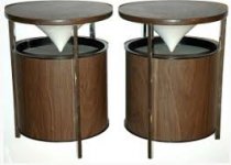
Nice idea to add a sub to your M2 (while I always loved the JBL basses ;-)
I have never experimented this (so, take-it with a pinch of salt) but i remember that somebody (The clever Earl Geddes ?) proposed to place several little sub bass enclosures at various places in the room instead of a big big one. The idea was they will excite different modes of resonances in their different places, so less impact of thoses. The second, for those who like closed boxes, you can build them with various resonances frequencies. Same remark.
Of course, due to the low frequencies involved and so the long wavelengths, no problem of phase between them.
NB: When I talked about 2 ways, I don't consider subs as a way, If you cut them low enough. More a sensurround one ;-)
Neither super tweeters that I don't use any more. Old Age ?
I'll measure the thd vs freq and where it starts to rise is where the cut-off will be placed (neglecting the thd dip at the port tuned freq).
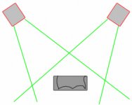
A method that rids us of the room again is to place the sub right beside you facing up. Low power is needed and thus low distortion from driver(s). No room influence between you and your ears.
Together with "controlled" 60-90 degree dispersion and close sub/bass you have essentially a near field situation.... and somewhat like headphones .. no room influence. Greater accuracy again towards hearing only the source.
Unfortunately these drivers are too large as would be their cabinets for them to be used that way. But I might find smaller drivers and do just that. Meanwhile, these large subs are primarily to cover the freq below 40Hz-50Hz with authority. Also, for movie SEffects.
THx-RNMarsh
Last edited:
HF radio is becoming unusable in built-up areas. The noise is gradually creeping up to VHF too. Radio amateurs are the 'canaries in the coal mine', as they are the first to suffer. Later it will be emergency services, who will find that their comms fails.RNMarsh said:In practice, i dont find there is a working issue. I have wireless and PLC in same area with zero issues of interference. Quit robust systems.
- Status
- Not open for further replies.
- Home
- Member Areas
- The Lounge
- John Curl's Blowtorch preamplifier part III