Yes, good stuff! The result, that to a first approximation high loop gain reduces distortion from the inverse function, can be arrived at by a bit of hand-waving from thinking about how high levels of feedback works. For simplicity assume close-loop gain of 1, so all the output is sent back and subtracted from the input. Then the signal driving the forward gain is just the error signal. This has to be approximately equal in shape to the inverse of the forward distortion, as the result at the output is relatively undistorted. Negative feedback forces distortion cancellation, approximately.janneman said:Any thoughts, anyone?
The output is then input minus the error signal, which is the inverse of the forward function. Hence the distortion in the output is approximately the inverse of the foward function. Actually someone (Baxandall?, Scroggie?) pointed this out years ago, possibly in the context of an emitter follower.
This means that if we want low distortion (ar at least, low order distortion) with high feedback then we need to choose a forward function which has a nice clean inverse. The ideal would be perfect linearity, but if we could do that we would not need feedback. Second best would be an inverse function with only small amounts of second-order and/or third-order. If f^-1=x+ax^2, where 'a' is small, what is f? Well, you have to solve a simple quadratic equation then use the power series expansion of sqrt(1+z). It would be nice if there were some physically realisable forward functions which have a nice inverse, but I suspect we won't find any.
One snag: this applies to algebraic systems with no memory. Real life is more messy!
Last edited:
Jan,
This is quite interesting...
Here another take on the same stuff...
harmonics
I am still thinking my way through things (for years now)...
[snip]Ciao T
Thanks, good link. I believe Renardson and Bruno should be in agreement (but with Bruno you never know
") ).
).jan didden
Please bring it on, and in the name of science of course.....So stay with me as I show the difference between none, local, degenerative and global feedback and what actually happens!
Eric.
Nothing new, but worth a reminder; graceful handling of clipping is important. I've known designers who never looked inside the loop to see what happened during clipping. It can get pretty dramatic inside during open loop conditions.
Hi Curmudgen,
This is very true. As mentioned in my book, it is very important to keep transistors out of saturation, and Baker clamps or flying catch diodes help a great deal. Some of these techniques are covered in my book. Of course, a good adaptive soft clip circuit is great, as long as those who use it are comfortable with the onset of distortion at a lower output power level before clipping. Such a circuit prevents the amplifier-proper from ever clipping. Well-deigned feedback amplifiers recover from clipping very fast.
Cheers,
Bob
Yes, good stuff! The result, that to a first approximation high loop gain reduces distortion from the inverse function, can be arrived at by a bit of hand-waving from thinking about how high levels of feedback works. For simplicity assume close-loop gain of 1, so all the output is sent back and subtracted from the input. Then the signal driving the forward gain is just the error signal. This has to be approximately equal in shape to the inverse of the forward distortion, as the result at the output is relatively undistorted.[snip]
Hmmm... I vagely remember an article where the author worked backwards from the output to calculate the input distortion, something like that.
Now where could I have that...
jan didden
Jan,
True. Looking at the data it would seem we would want around 30-40dB NFB minimum, at high (supersonic) frequencies within the amplifiers passband, combined with suitable and reliable measures against the ingress of high frequency noise above this bandwidth on both input AND output, in order to remove the potential for IMD products of said being of substantial levels folding back into the audio range.
I am hard pressed to come up with actual examples for such amplifers, maybe Stochino's "ludicrous speed" amp from EWW? This may have enough feedback at high frequencies, but probably not.
Alternatively of course one may concentrate on the open loop linearity and on minimising higher order harmonics in what cannot be avoided and use only modest NFB with a very wide open loop bandwidth, primarily to help at high (power) levels.
Of course, this then leads us towards even more esotheric schemes, such as feed forward error correction to linearise output stages, or any of the other alternatives...
But we are back at the point that "misapplied NFB" can cause as many probems in other areas than it solves in the one of the main investigation (e.g. LF THD).
Ciao T
Thanks, good link. I believe Renardson and Bruno should be in agreement (but with Bruno you never know
True. Looking at the data it would seem we would want around 30-40dB NFB minimum, at high (supersonic) frequencies within the amplifiers passband, combined with suitable and reliable measures against the ingress of high frequency noise above this bandwidth on both input AND output, in order to remove the potential for IMD products of said being of substantial levels folding back into the audio range.
I am hard pressed to come up with actual examples for such amplifers, maybe Stochino's "ludicrous speed" amp from EWW? This may have enough feedback at high frequencies, but probably not.
Alternatively of course one may concentrate on the open loop linearity and on minimising higher order harmonics in what cannot be avoided and use only modest NFB with a very wide open loop bandwidth, primarily to help at high (power) levels.
Of course, this then leads us towards even more esotheric schemes, such as feed forward error correction to linearise output stages, or any of the other alternatives...
But we are back at the point that "misapplied NFB" can cause as many probems in other areas than it solves in the one of the main investigation (e.g. LF THD).
Ciao T
Hi Bob,
Let's try to look forward, then.
You all remember the (in)famous 'Baxandall curves' showing increase in distortion with feedback in some area's. This was extensively discussed and explained in Bruno Putzeys' article in Linear Audio Vol 1.
Menno van der Veen, another successful (tube) designer, commented on that and surprisingly, Bruno's reply also contains an interesting conclusion about the 'law' behind those 'Baxandall curves' once you get over the 'hump'.
The letter exchange is here:
http://www.linearaudio.net/userfiles/file/letters/Volume_1_LTE_MvdV.pdf
Any thoughts, anyone?
The figure Bruno uses in his conclusion is attached.
jan didden
Hi Jan,
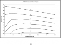
Unfortunately Bruno did not tell the whole story on the "Baxandall distortion". The three figures below are from Chapter 24 in my book. The first is akin to Baxndal's, where the distortion of a single JFET stage is shown as a function of NFB. This shows the effect, where some distortions increase until the NFB reaches about 15 dB.
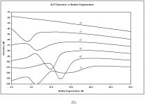
Unfortunately few amplifiers are built from a single square-law device. BJTs themselves are of course not squarelaw. The second figure shows this distortion effect for local negative feedback in the form of simple emitter degeneration of a single BJT stage. Yes, even NFB in the form of "benign" emitter degeneration shows the effect!
As explained in the book, the point at which this distortion from a given stage decreases depends on the total amount of NFB around the stage, including all forms of local NFB.
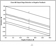
Finally, the effect is not even seen in the more complex situation of an output stage, where increasing NFB ALWAYS reduces all orders of distortion, as shown in the third picture from my book.
So much for this distortion in the real world. It is largely a red herring.
Cheers,
Bob
Attachments
Well. it is nice to see a good technical discussion! The amplifiers with grid leak bias have three different operating points. The first stage has about 50 volts swing the middle 25 and the final 60!
When I do global feedback on the three stages the results are terrible. The first stage shows a very distorted waveform, that gets amplified by the following stages all out of clipping.
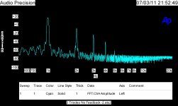
Attached is the slightly surprising distortion of three stages of amplification and a single stage with "Global" feedback via a 750K resistor bypassed with 2.5 Pf.
When I do global feedback on the three stages the results are terrible. The first stage shows a very distorted waveform, that gets amplified by the following stages all out of clipping.
Attached is the slightly surprising distortion of three stages of amplification and a single stage with "Global" feedback via a 750K resistor bypassed with 2.5 Pf.
Attachments
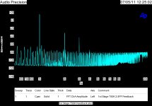
When I do global feedback on the three stages the results are terrible.
Well, with multiple zeros, not staggered, and multiple poles, also not staggered, this is no great surprise.
Well, with multiple zeros, not staggered, and multiple poles, also not staggered, this is no great surprise.
Thanks for one obvious conclusion, I think there are many more from what is shown.
I like the missing IM products!
Oh yeah the feedback works exactly as expected!
Anyone want to guess what would happen if Bipolar Junction Transistors were used in a similar configuration with only a collector and single (selected) bias resistor?
PS, the German heading is not really translatable
Sure it is.
Chamber of Horrors. Also the "Haunted House Ride" or "Ghost Train" at the fairgrounds or fête.Hi,
I was referring to a specific amplifier design published in WW, which was lauded especially for the high slew rate in shorthand (those versed in the arts will know which design I speak of).
I made very clear that, if wish to to minimise the risk of high frequency intermodulation causing trouble where it matters, then we need a lot of NFB at relative high frequencies or good inherent linearity at high frequencies...
BTW, there are also Op-Amp's that have open loop bandwidth in the regions of 10's of KHz or more and >> 1000V/uS Slewrate. Oh, not to forget, vanishing low THD1M... But it seems you have not heard of them...
Ciao T
Last time I looked, open loop bandwidth had squat to do with speed. The are op amps (and by implication, power amplifiers) with open loop bandwidths of a few tens of Hz that easily do 100V/uS slew rate.
I was referring to a specific amplifier design published in WW, which was lauded especially for the high slew rate in shorthand (those versed in the arts will know which design I speak of).
I made very clear that, if wish to to minimise the risk of high frequency intermodulation causing trouble where it matters, then we need a lot of NFB at relative high frequencies or good inherent linearity at high frequencies...
BTW, there are also Op-Amp's that have open loop bandwidth in the regions of 10's of KHz or more and >> 1000V/uS Slewrate. Oh, not to forget, vanishing low THD1M... But it seems you have not heard of them...
Ciao T
Hi,
Ah, I did not analyse the circuit not enough. As shown your results are not surprising. The two stages that have the most distortion are in phase with each other, so are the distortion products, so the they add and the effects of distortion cancellation and multiplication are reduced.
While the feedback you described is looped, it is NOT global, it is local.
The results of the feedback case is also unsurprising, as the linearity of the stage that combines signal and feedback is poor.
Try it with the levels and distortion levels increasing from stage to stage with most in the final stage, so that it more represents the way a real amplifier works. Using a circuit with equal levels in each stage may also be be rather interesting...
Ciao T
Well. it is nice to see a good technical discussion! The amplifiers with grid leak bias have three different operating points. The first stage has about 50 volts swing the middle 25 and the final 60!
Ah, I did not analyse the circuit not enough. As shown your results are not surprising. The two stages that have the most distortion are in phase with each other, so are the distortion products, so the they add and the effects of distortion cancellation and multiplication are reduced.
Attached is the slightly surprising distortion of three stages of amplification and a single stage with "Global" feedback via a 750K resistor bypassed with 2.5 Pf.
While the feedback you described is looped, it is NOT global, it is local.
The results of the feedback case is also unsurprising, as the linearity of the stage that combines signal and feedback is poor.
Try it with the levels and distortion levels increasing from stage to stage with most in the final stage, so that it more represents the way a real amplifier works. Using a circuit with equal levels in each stage may also be be rather interesting...
Ciao T
Hi,
This translates the words, not the cultural context...
BTW, what you think it is, is actually called "Geisterbahn" in German, literally "Ghost Train".
Ciao T
Sure it is.
This translates the words, not the cultural context...
BTW, what you think it is, is actually called "Geisterbahn" in German, literally "Ghost Train".
Ciao T
Hi,
Another request, please keep the scales consistent for the different displays, that is either both cases down to -140dB or down to -100dB, it minimises mistakes in interpretation.
Ciao T
Well. it is nice to see a good technical discussion!
Another request, please keep the scales consistent for the different displays, that is either both cases down to -140dB or down to -100dB, it minimises mistakes in interpretation.
Ciao T
Hi,
While the feedback you described is looped, it is NOT global, it is local.
Ciao T
Looped is a good term, I wanted to make it clear it was not a cathode resistor.
Yes one of the issues to be demonstrated is how a high gain low distortion amplifier can be used to reduce overall distortion of a complete system.
Also how ganging two high gain stages may not offer advantages.
Right now I am still adding to the list of tests to run.
I am changing scales to get detail, when I do publication runs, I will try to keep scales the same, but this is still a work in progress.
Hi,
I used above the following nomenclature:
1) Degeneration = non-looped local current feedback (unbypassed Cathode/Source/Emitter resistor)
2) Local Feedback = (voltage) shunt feedback looped around a single active device (which is not an IC)
3) Global Feedback = (voltage) shunt or series feedback looped around two or more active device (or a single or more IC's)
Try to come up with some no-one has yet done.
Sure, but side by side visual comparisons are very powerful tools, if the plots are comparable... So consider this a "pretty please" from me. You can always add a zoomed version to the set...
Ciao T
Looped is a good term, I wanted to make it clear it was not a cathode resistor.
I used above the following nomenclature:
1) Degeneration = non-looped local current feedback (unbypassed Cathode/Source/Emitter resistor)
2) Local Feedback = (voltage) shunt feedback looped around a single active device (which is not an IC)
3) Global Feedback = (voltage) shunt or series feedback looped around two or more active device (or a single or more IC's)
Right now I am still adding to the list of tests to run.
Try to come up with some no-one has yet done.
I am changing scales to get detail, when I do publication runs, I will try to keep scales the same, but this is still a work in progress.
Sure, but side by side visual comparisons are very powerful tools, if the plots are comparable... So consider this a "pretty please" from me. You can always add a zoomed version to the set...
Ciao T
[snip]...
But we are back at the point that "misapplied NFB" can cause as many probems in other areas than it solves in the one of the main investigation (e.g. LF THD).
Ciao T
Coincidently, I just received another Letter to the Editor on this (related) subject from Marcel van de Gevel. He points out that when you squash the LF gain by for instance a resistor-load on the Vas, the overshoot of the input signal will disappear but only because the final error value increases.
Iow, instead of an overshoot of, say, 1V and a final value of, say 0,2V, you now get an overshoot of 1V and a final value of 1V. Of course that doesn't look like overshoot anymore but nevertheless is a giant step backwards wrt linearity of the amp.
See http://www.linearaudio.net/userfiles/file/letters/Volume_1_LTE_MvdG.pdf
jan didden
- Status
- Not open for further replies.
- Home
- Member Areas
- The Lounge
- John Curl's Blowtorch preamplifier part II