I am talking 'HISTORY' here, I have not gone any farther than 1980. Let's talk about the time and place, NOT your 'hindsight' today. We have worked on plenty of other stuff, since 1980, but not relating to TIM. What we ALSO found as important in audio design is beyond discussion at this point, on this thread.
Now, we are at 1980 +/-. TIM has been 'put to bed' so to speak, Japanese jfets are becoming popular, and I am working for myself, with a minimum of lab equipment, so no more direct research from me, for awhile. In this time period, I designed 3 master tape recorders, 2 eight channel mixers, and 2 moving coil pre-preamps, two power amps, and started on the Dennisen JC-80 all fet preamp with phono and added switching. Ultimately, this preamp made 'preamp of the year' in Japan.
Here, we had the ability to make the best preamp ever, so we put a lot into it. It was dual mono, used P&G linear volume controls (just like the pros), hermetic relay switching, an open loop phono input stage, direct coupling, servos, ground planes, etc. We made a few mistakes too, and hindsight (like what Scott likes to use) would be applicable here. Still, it competed with the best of them for about 10 years.
Vendetta was not started as yet, and it basically obsoleted the JC-80 in subsequent years. (more later)
Now what did we learn TIM that can be used today?
First, 5V/us for preamps and 50V/us for a 100W power amp was found to be a reasonable guideline.
Second, there was lots of ultrasonic garbage, mainly from MC phono mistracking, but other sources were possible, and this had to be passed cleanly, and this is what raised the TIM guidelines.
Third, that was NOT all there was to making amp and preamp nirvana. We were missing some factors: PIM, high peak current, very low level higher order distortion? All three, probably.
For example, I made a power amp with over 1000V/us, 30 amps peak output, and 64W class A operation and 240W class AB operation, YET it failed to satisfy the client over a long period of time. What was wrong? What could I have changed? People here would have thought my effort, exotic, and over the top, BUT it still was not completely successful. (more later)
In the 1980's much of effort in audio design went to digital. You know, 'Perfect sound forever', and not much improvement was sought in analog design.
Still, we had some sidelights, one of which was CAPACITOR 'error' both linear and non-linear, and self resonance. This led to direct coupling of almost all designs, sometimes using servos, and sometimes using close matching to achieve this. In any case, we found that coupling capacitors, mostly, were a problem. A great deal of controversy was started between Doug Self and me over this, that went on for years. Ultimately, Walt Jung and I published a practical measurement of linear distortion in caps, actually being partially helped at the time by Scott Wurcer and Bob Pease, due to their own research. By the end of the decade, it was pretty much settled, and polypropylene, polystyrene or Teflon caps were chosen where they were necessary. This was true with the JC-80 and any following preamps I have ever designed, ever since. (more later)
Still, we had some sidelights, one of which was CAPACITOR 'error' both linear and non-linear, and self resonance. This led to direct coupling of almost all designs, sometimes using servos, and sometimes using close matching to achieve this. In any case, we found that coupling capacitors, mostly, were a problem. A great deal of controversy was started between Doug Self and me over this, that went on for years. Ultimately, Walt Jung and I published a practical measurement of linear distortion in caps, actually being partially helped at the time by Scott Wurcer and Bob Pease, due to their own research. By the end of the decade, it was pretty much settled, and polypropylene, polystyrene or Teflon caps were chosen where they were necessary. This was true with the JC-80 and any following preamps I have ever designed, ever since. (more later)
Where were we? Oh yes, capacitors. Even today many engineers use problematic caps with impunity, but they can be measured in several different ways, and found to be almost laughable in some cases.
Going back to the early '70's, and before, almost all audio designs used lots of coupling caps. It didn't matter: Ampex, Studer, Revox, Marantz, Dyna, etc all used electrolytic coupling caps. First, to support a single voltage power supply, and later, to avoid servos. Often, Solid Tantalum caps were used then, as they were considered available, cheap, and small. Sometimes 2.2 uF ceramic caps were used, as they were bipolar, small, often rather attractive looking. However, they were relatively expensive at the time. While certain aspects of capacitor limitations were deemed important in some applications, such as sample and hold circuitry, it was generally acceptable to use just about any cap that did not show an overt problem when measuring SMPTE IM distortion of the entire assembly. The lessons previously learned by Analog Computer Engineering were soon forgotten, and cheap and small became an overwhelming choice. (more later)
Going back to the early '70's, and before, almost all audio designs used lots of coupling caps. It didn't matter: Ampex, Studer, Revox, Marantz, Dyna, etc all used electrolytic coupling caps. First, to support a single voltage power supply, and later, to avoid servos. Often, Solid Tantalum caps were used then, as they were considered available, cheap, and small. Sometimes 2.2 uF ceramic caps were used, as they were bipolar, small, often rather attractive looking. However, they were relatively expensive at the time. While certain aspects of capacitor limitations were deemed important in some applications, such as sample and hold circuitry, it was generally acceptable to use just about any cap that did not show an overt problem when measuring SMPTE IM distortion of the entire assembly. The lessons previously learned by Analog Computer Engineering were soon forgotten, and cheap and small became an overwhelming choice. (more later)
Last edited:
Repetition is necessary when professionals and amateurs alike appear to have little or no regard as to how much sonic damage they are doing by using inappropriate capacitors in audio projects.
In all fairness, I was 'clueless' for the most part, 40 years ago, yet my design topologies were very advanced.
I used ceramics, Mylar, mica, tantalum, aluminum caps, for the most part. YET, sometimes they seemed to be part of the problem, but HOW? That was the question. It was NOT on the data sheet.
In 1974, the breakthrough came for me, when Tektronix showed me the 'transfer function' of a typical ceramic cap. It was amazingly lousy. Kind of like the 'transfer function' of a 741, open loop! Once I found out how to measure caps the way Tek did, I got Mark Levinson to remove all ceramic caps where we were using them in the JC-2.
I went on a campaign against these caps and pushed for mica or mylar, instead. It wasn't until 1977 or so, working with the Symmetry Xover, that Noel Lee insisted that he could hear the Mylar coupling caps in the design. I didn't believe him, at first, but he was right. What was going on? This is when Dick Marsh started talking about dielectric absorption in audio caps, and this seemed to fit. The cap article in 'Audio' by Jung and Marsh settled it, no more coupling caps, if possible.
Independently, in 1978, I published low frequency distortion in Tantalum caps when used as feedback caps in preamps and power amps. This also pointed to using servos, but this still was relatively impractical. (more later)
Last edited:
What else did we look into? Well, resistors, connectors, circuit board material, layout, shielding, grounding, etc. That's what!
We attacked each and every of these topics, trying EMI line filters for example, trying different brands of resistors, using better than FR4 circuit board material, HEAVY gold on gold connectors, advanced circuit layout, heavy aluminum boxes, etc.
When it came to commercial EMI line filters, we found that they were as problematic as the problem they were designed to solve. Ceramics again? I'm not sure.
Resistors: Several good 1% resistors were found, Corning Grey, Resista, Dale (in some cases), Vishay bulk metal. I settled on Resista.
As far as RCA connectors go, the Tiffany RCA connectors could not be beat. They were thick gold plated, and tight fitting, beautifully made. You could have a tight, secure connection and not worry about 'breaking' the RCA connector away from its mounting.
Later, they made an even more exotic RCA connector with thick gold plating directly over OHFC copper, with NO nickel interface. I shudder to think what they cost today, even OEM.
We also got into the physics of solder, it's optimum configuration and how to use it. We started using special solder 'servers' that kept human fingers off the solder, when making a connection.
Etc, etc. (more later)
Hi John,
Just writng an article in Audio is certainly not a "takeover" of the subject, nor was it intended to be. It is silly of you to imply that five guys would feel sole ownership of the subject, and you should only speak for yourself in this regard. I have both the original from you and the rebuttal from me, and maybe I'll get around to PDFing it and putting it up here so people can see what is there without your distortions. As with many other things where you choose to re-write history, your characterization of Gene Pitts' actions and views in that matter are quite distorted.
Cheers,
Bob
If people feel the need to 'own' a subject, then DONT PUBLISH. Its as simple as that. Your work(s) then remain concealed from the public domain, and people that don't have that knowledge have to battle through until they develop it or discover it.
One of the reasons papers or articles are written in science and engineering is so that they are open to critique, interpretation and further discussion . . . thats how knowledge is shared and expanded.
Ottala (spelling?) et al published his work in the 70's, Cordell had a different interpretation and published his work in the early 80's. There is a difference of technical opinion. No amount of discussion about the historical chronology will change that!
Now for a slight change in path. In the early 80's, I came up with the topology that became the Vendetta Research input stage. It started as a pre-preamp that measured, open loop about 100 times better than the SOTA head amp, or for that matter, the JC-1. It also operated at 10 times the voltage and 30 times the current as well, so it HAD to be AC powered. Batteries just would not do, as they were too large, expensive, etc. This meant a 2 box design with the AC-DC conversion in one box and the phono gain stage in the other. This is generally the best way to do it, although a one box implementation is possible with a lot of shielding. Distance is the KEY to easy hum reduction between the transformer, etc and the sensitive gain circuits. Good layout is also necessary, and even a battery powered unit will hum, if the layout is lousy, due to the residual AC from nearby AC sources. The Vendetta started out in a plastic box, painted with conductive shielding paint, with a +/- 15V regulated supply that OEM'd at the time for about $25. Such a deal! It didn't stay that way, however, it kind of 'grew up' over time. (more later)
Walt remembers testing the 1741S. [snip]
John, maybe you should remember Walt's research as well.
jan didden
Attachments

Jan, I did not research SID with Walt, so I haven't memorized every passage of his work. However, thanks for the input.
In 1976, when I was working in Oulu, on the TIM paper, a Finnish audio magazine or local paper, interviewed me about TIM, without Matti present. They asked me about the same thing, i.e. open loop bandwidth vs TIM, and I told them the same thing that Walt did, because after reading Solomon's paper on OP AMP design, published in 1974, in the 'IEEE Journal of Solid State Circuits Vol SC-9, No. 6' the derivation of slew rate vs input stage Gm became obvious, and open loop vs slew rate was a secondary consideration.
I upset Matti at the time, with my admission of these statements to the local 'press' but I am pretty sure they were either in Finnish or Swedish, so I could not further comment. (Sorry Matti, but 'warts and all' is necessary for clarity)
Jan, I did not research SID with Walt, so I haven't memorized every passage of his work. However, thanks for the input.
[snip]
Sure.
It would be good to know whether or not you agree with Walt's research in this.
Might put one more confusion to rest.
jan
Attachments
Neither Walt or I necessarily agree with that statement, in that EXCELLENT SID MEASUREMENTS DO NOT NECESSARILY MAKE GREAT AMPLIFIERS. This is why both of us are solidly behind PIM as a fundamental contributor, AND I know for sure that Walt, today, is a firm believer in high open loop bandwidth. He confirmed it, just this week, in a phone call.
With regards to the problem, we appear to be coming to an understanding as to why Matti was so adamant to keep 'open loop bandwidth' as an important contributor. After all, typical worse case TIM was not all that bad, and his and Jan L's power amp really sounded extra good, so something must be 'right' about high open loop bandwidth, and he apparently just wasn't sure yet, himself what. At least he could not PROVE it with TIM theory and measurement.
From the input that I got from Mitch Cotter, he was the one to put Matti on track with differential phase distortion and how it could be minimized by high open loop bandwidth, just like the video amp designers do it. Matti mentioned 'differential phase distortion' to me back in 1978, when we were still working together, but I was relatively 'clueless' at what it meant at that time, except that I was using the Electrocompaniet power amp at home, and it had a deliberately made, 'high open loop bandwidth' and it sounded better to me, than all the rest of the solid state commercial amps that I compared it to.
From the input that I got from Mitch Cotter, he was the one to put Matti on track with differential phase distortion and how it could be minimized by high open loop bandwidth, just like the video amp designers do it. Matti mentioned 'differential phase distortion' to me back in 1978, when we were still working together, but I was relatively 'clueless' at what it meant at that time, except that I was using the Electrocompaniet power amp at home, and it had a deliberately made, 'high open loop bandwidth' and it sounded better to me, than all the rest of the solid state commercial amps that I compared it to.
Would you kindly link to a relevant PIM article or paper by Walt Jung? Jan's question is perfectly legitimate.
I certainly do know this one:
http://waltjung.org/PDFs/WTnT_Op_Amp_Audio_3.pdf
I certainly do know this one:
http://waltjung.org/PDFs/WTnT_Op_Amp_Audio_3.pdf
Last edited:
[snip] AND I know for sure that Walt, today, is a firm believer in high open loop bandwidth. He confirmed it, just this week, in a phone call.
Well that's funny. In his AES paper, Walt says:
(I'll write it out in case you have issues with my attachments)
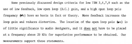
"Some previously discussed design criteria for low TIM, such as the use of low feedback, low open loop (D.C.) gain, and a high open loop gain frequency (W0) have no basis in fact or theory. More feedback increases the loop gain and decreases distortion. The location of the open loop pole (W0) is of little significance to audio designers, and it does not (his underline) have to be placed at a frequency above 20kHz for superlative performance to be obtained. Our measurements support these statements."
Do you agree with Walt?
jan
Last edited:
I hope that Walt might join our discussion, as he time after time does, and place his opinion on necessity of high openloop wo, without 'translation' by someone else. I do not mean your citation, Jan.
Pavel, I reread the paper in your link, which I also have in my library. I have most of Walt's papers, as they always have good information that has practical use.
This paper however could have been clearer.
Walt is of course correct that amplifiers with higher open loop gain are better than lower open loop gain, all else being the same. Problem is, all else is not the same.
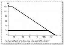
See attached, which shows (top) the OL freq response of an opamp with an OL corner of about 10Hz. I think we all agree that qualifies as 'low OL bw'. There would be little discussion that with increasing freq, the feedback becomes less effective, the error signal increases and if you get into the curved part of the input stage Gm, you may get PIM. Not good.
So, let's fix it: we put a resistor from the Vas output to ground and presto: we have the bottom curve which is a VERY wide OL bandwidth opamp.
Unfortunately, this doesn't help us AT ALL. Remember, the PIM results from Gm modulation due to the high error signal at the LTP input. With our 'fix', we only INCREASED the error voltage at lower frequencies, and DID NOT DECREASE the error signal level at higher frequencies. So our fix results in: a) a nicer, flatter OL response, and b) more distortion and more non-linearity, including PIM, at the output.
Is that what we want? Just cosmetics, and to hell with the performance?
jan
Attachments
- Status
- Not open for further replies.
- Home
- Member Areas
- The Lounge
- John Curl's Blowtorch preamplifier part II