Scott, I think it was you, that link (seems to be deleted now) you posted to Breaux Freres-Ma Blonde Est Partie is the BEST music I've heard all year!
You're welcome it was probably me. There's a large body of recordings where there are no masters so this is what you get.
Richard, VAS is the best BJT available. The bias certainly affect 'kinks', here is with 300 mA.
Damir
Thank you. I came to the 200mA after some study with distortion vs idle.
It gets the heat sink fairly warm. So, we will stay with 200Ma... the sim is great and fast. Looks perfect... no kinks.
Lesson learned -- It would appear that setting bias via thd minimum is still effective way.
THx-RNMarsh
Last edited:
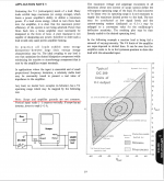
I remember having first seen this use of a stereo set to measure the output impedance of an amplifier in an AP publication (named audio.tst) back in ~1990/1991, but i don´t know if they or someone else invented it.
Here is a chunk from my Audio Amateur HK-12 article from 1981.
Attachments
Here is a chunk from my Audio Amateur HK-12 article from 1981.
Thanks a lot, not only for the information but for the nice idea too.
Who has invented it? Ricola.......err, um... Nelson
")
It's obvious enough that it must have been done before me.
I thought I saw the technique in the mid to late seventies but not clear where. It may have been in the original Crown DC300 owners manual. Not the later version that had lots of material removed.
Here is a chunk from my Audio Amateur HK-12 article from 1981.
Yes, very basic way to test for Zo. A voltage and a current probe can help with very low Z measurements.
But many opamps are not very simple in their output Z ;
http://www.ti.com/lit/an/slyt677/slyt677.pdf
THx-RNMarsh
Last edited:
It's obvious enough that it must have been done before me.
"Diagnosis of Distortion. The "Difference Diagram" and its Interpretation" by Edmund Ramsay Wigan
Hi-Fi News & Record Review, F.Jones, "Dynamic testing of audio amplifiers", November 1970
http://www.keith-snook.info/wireles...ble amplifier distortion is not a mystery.pdf
Last edited:
First order, it is reduced by the ratio of it's output impedance to the
impedance between the channel outputs, aka DF.
yes, of course. I referring to non-linear elements in source Z driving non-linear output Z. Over a range of freq and phase.
-RM
I thought I saw the technique in the mid to late seventies but not clear where. It may have been in the original Crown DC300 owners manual. Not the later version that had lots of material removed.
No but what you remember is a very useful test nevertheless

Pdf page 22 (19 on original)
https://adn.harmanpro.com/site_elem...C-300-Instruction-Manual-dc300im_original.pdf
George
Attachments
"Diagnosis of Distortion. The "Difference Diagram" and its Interpretation" by Edmund Ramsay Wigan
Hi-Fi News & Record Review, F.Jones, "Dynamic testing of audio amplifiers", November 1970
http://www.keith-snook.info/wireless-world-magazine/Wireless-World-1977/Audible%20amplifier%20distortion%20is%20not%20a%20mystery.pdf
Good stuff there rayma, thanks, Keith-snook took a lot of time and effort to write that up.
And of course George is a never ending source of amazement with the resources he finds.
Well at least all of the resources except the ONE he couldn't find of the composit pictutre
of the worlds most infamous dictators.
and I was in Athens at the time. Parakahlo
Last edited:
except the ONE he couldn't find
That’s a grave point in my CV. I can’t get rid of it

George
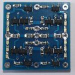
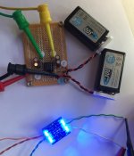
Wanting to know how well a Blowtorch-like topology built with lower gm FETs might perform, we went ahead to get hold of and matched a bunch of 2SJ106Ys, 2SK208Ys and 2SK209GRs.
The frontend diff pair is biased at 1mA, the IV resistor is 15k, and the output is buffered by a pair of 2SK209GR source followers.
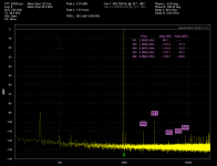
Performance exceeds my expectation, especially the low output noise.
And most important it was a lot of fun.
Patrick
.
The frontend diff pair is biased at 1mA, the IV resistor is 15k, and the output is buffered by a pair of 2SK209GR source followers.
Performance exceeds my expectation, especially the low output noise.
And most important it was a lot of fun.
Patrick
.
Attachments
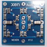
The FET models are already in the Spice file.
There is no point in specifying the resistor values as they depend on the Idss of the devices as well as the desired gain.
For our test build, we chose FETs for the gain block around 2.5mA, and degenerated them to 1mA.
The exception is the output source follower, which have Idss~5mA, but the exact value is not important.
As already mentioned, the IV resistor is 15k, and the resistor between the front end diff pair is trimmed to the required gain.
In our case, we used a gain of 10.
Patrick
- Status
- Not open for further replies.
- Home
- Member Areas
- The Lounge
- John Curl's Blowtorch preamplifier part II