You can extend their lifetime by inserting some 47Ohm resistor into the pos supply line. This restricts current consumption below latchup hold current thus preventing drawing excessive current after latchup triggering.the cmos timers are easy to blow up though
(compared to bipolar)
If you are lucky you might still find genuine 2SK246/2SJ103 etc.
I bought "Fairchild" 2N5457 / 2N5460 from AliExpress, as did Richard Marsh. Much cheaper than the current production from Central Semiconductor.
Hey Scott,
Sent ya an e-mail, didja get it?
John
I sent you my new preferred email, the old one backs up since I only check it once a week.
Watch out or I'll start the hubris generator."Notes fade to absolute darkness, the speakers simply disappear, even the LA Philharmonic sounds compelling..."
Next you'll be saying the circuit makes the vocals on your old Shaggs LP sing in tune...
lolol
Howie
yes, Jan "flat gain" is worse below the corner, but why not 2-pole
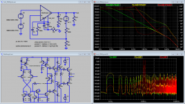
amp from Bob's book - 3 compensations:
green trace - nominal dominant pole
yellow trace - added 300k R, R||Cdom to flatten gain, get "wide open loop gain" (couldn't load the beta enhanced VAS out heavily enough with shunt R to gnd)
red trace - 2-pole
we could examine green vs yellow 1K IMD diff phase - and they do differ by ~90 degrees which could be interpreted as one being "AM" and the "FM/PIM" IMD
at best for John's/Otala's formulation the dominant pole "low open loop bandwidth" has 25 dB less error at 1KHz, leaving "pure FM/PIM" residual vs the "flat gain" case
there is no reason to believe the phase relation makes "PIM" order of magnitude more audibly objectionable than "AM" IMD
and then there's the 2-pole red trace IMD components...
also note that 2-pole compensation is the only one showing a 20 dB improvement in the 21kHz IMD sum distortion product amplitude
How about this thought experiment: I have this great amplifier with the usual Cdom around the Vas stage. It has an OL BW of 20kHz at an OL gain of say 60dB.
Now I am increasing the Vas stage load impedance, with the same Cdom. I believe the result would still be 60dB @ 20kHz, but increasing OL gain toward lower frequencies, like 72dB at 10kHz and 84dB at 5kHz etc, and I continue until the OL BW is reduced to 10Hz, where it has a very high gain.
I believe that the 2nd amp is much more linear and transparent in the main audio listening frequency range. Or is there something I overlook?
Jan
amp from Bob's book - 3 compensations:
green trace - nominal dominant pole
yellow trace - added 300k R, R||Cdom to flatten gain, get "wide open loop gain" (couldn't load the beta enhanced VAS out heavily enough with shunt R to gnd)
red trace - 2-pole
PIM distortion?
we could examine green vs yellow 1K IMD diff phase - and they do differ by ~90 degrees which could be interpreted as one being "AM" and the "FM/PIM" IMD
at best for John's/Otala's formulation the dominant pole "low open loop bandwidth" has 25 dB less error at 1KHz, leaving "pure FM/PIM" residual vs the "flat gain" case
there is no reason to believe the phase relation makes "PIM" order of magnitude more audibly objectionable than "AM" IMD
and then there's the 2-pole red trace IMD components...
also note that 2-pole compensation is the only one showing a 20 dB improvement in the 21kHz IMD sum distortion product amplitude
Attachments
Last edited:
actually looking at the red 2-pole trace there is a good case for human hearing purposes that @ -160 dB the 1 kHz IMD product (the vector sum of "AM" and "FM/PIM") "doesn't exist"
please cite any reference to human listening tests of the audibility of +/-90 degree rotation of -60 dB harmonic and IMD product phase
or link to a piece of hi res music or test tone that you think would make "PIM" clearly audible and we can process it with "Hilbert transformer" I/Q sideband math and post for listening tests
actually looking at the red 2-pole trace there is a good case for human hearing purposes that @ -160 dB the 1 kHz IMD product (the vector sum of "AM" and "FM/PIM") "doesn't exist"
please cite any reference to human listening tests of the audibility of +/-90 degree rotation of -60 dB harmonic and IMD product phase
or link to a piece of hi res music or test tone that you think would make "PIM" clearly audible and we can process it with "Hilbert transformer" I/Q sideband math and post for listening tests
You could make the case that the red 2-pole is so much better than the green low bandwidth because the two-pole 'artificially' extends the OL BW.
Jan
by eyeball I don't clearly see where the phase advance is coming from in the amplitude slope - maybe you're trying for a "fractional pole" slope?
so I wouldn't say without the circuit to sim, probe to move around
but there are examples of 2-pole commercial op amp gain curves, and built hardware where the sim inside the "error correction" looops show 2-pole + Bode Step
http://www.diyaudio.com/forums/soli...terview-error-correction-250.html#post1328496
http://www.diyaudio.com/forums/soli...terview-error-correction-337.html#post1513928
Lurie was trusted with Billion US$ spce project control design
http://www.diyaudio.com/forums/loun...ch-preamplifier-part-ii-8469.html#post4782512
Attachments
Last edited:
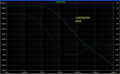
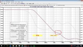
Maybe a bigger image with tangential line would help? As you know, even small changes in amplitude slope make huge difference in a phase plot. And here we go from -40dB/decade to -20dB/decade near 0dB crossing to get the system stable.
Attachments
Last edited:
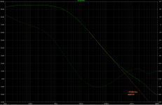
what's shown looks like adequate phase margin at the ulgf
but you don't show high enough f to see the gain margin and the phase seems too flat in the last few octaves without some gain peaking in the next to pull it up
how does it sim in .tran with ns t_step size?
but you don't show high enough f to see the gain margin and the phase seems too flat in the last few octaves without some gain peaking in the next to pull it up
how does it sim in .tran with ns t_step size?
Last edited:
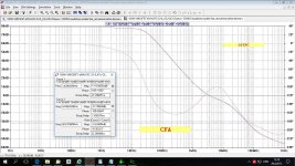
Here are two Bode plot examples, first one quite similar to PMA's and it's VFA with TPC and added Cherry cap from the output to the TPC middle point and other one is CFA with similar compensation. The CFA is working amp and very stable. Both Bode plots are extended up to 1 GHz to see the Gain Margins.
Attachments
- Status
- Not open for further replies.
- Home
- Member Areas
- The Lounge
- John Curl's Blowtorch preamplifier part II