Could you clarify? The standard differential A/D drivers use four resistors for feedback, it's inverting feedback so the FET's buy you nothing. I posted an idea a few weeks ago using a new THAT part to make a diff out in-amp with an external FET pair. Leadless package only, I'm not set up for that.
EDIT - It's the THAT 1580, built mine with an AD625 but this part is probably better for this.
Can you remember where you posted it? I did a search but only found your hydrophone sketch from October last year.
I know you also need a CM servo.
But then ordinary opamp such as OPA1641 will do for that job.
I also know you can use a dual opamp to make up the diff servo.
But a JFET-input OPA1632 would be much simpler.
Patrick
Used in its intended purpose that driver has 0 common mode at the output for any input common mode. I hope folks realize that. You in general don't want to pass common mode input signal at any frequency so the common mode loop acts at the full BW of the signal path.
Can you remember where you posted it? I did a search but only found your hydrophone sketch from October last year.
It was a horrible sketch so I trashed it, I'll make a new one.
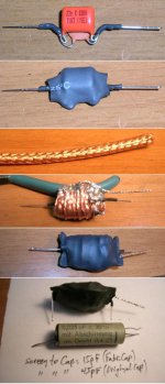
Naaah, I am sure the published capacitor guru is right and the Agilent capacitance meter is wrong.Maybe there is not a full layer of outer foil in all film caps? Maybe some of them look more like the image below from the side?
I was pretty happy to see Richard's technique but less happy to see Mark's so repeated the experiment. Cap was 10uF/100V PE and measured with the copper leads going directly into the terminals of a B&K meter (zero-checked before each measurement). The measurement was repeated with the B&K and also measured once using one of those cheap "measure everything" things on eBay.
Total measured capacitance either meter: 9.7uF
On one end with B&K: 87 and 87 pF
Other end of cap, B&K: 85 and 84 pF
With cheap thing: 85 and 84 pF on opposite ends.
Total measured capacitance either meter: 9.7uF
On one end with B&K: 87 and 87 pF
Other end of cap, B&K: 85 and 84 pF
With cheap thing: 85 and 84 pF on opposite ends.
Attachments
It is pretty clear on a round single section wound capacitor the outside foil should be connected to either the signal common or the higher potential side. On many capacitors the
Lead connected to the outside foil is marked with a band. Some use the lead on the left when reading the label to connect to the outside foil.
HOWEVER there are capacitors made up of multiple sections that are paralled. These can have alternating outside foils and not have an easily differentiated wilt wiring advantage
Of course there are some where there is extra insulation around the outside that would reduce external influences.
Of course we could have stacked foil construction or even shielded capacitors ala aluminum can units. Some of those are actually well sealed, even some specialty film units.
Last edited:
If cap construction doesn't show C difference between closest and further distance as a C change. There are other ways......
A high Z meter or scope input..... with cap across the input... touching the cap body will give increased noise pickup or not.
Demo here : https://youtu.be/ecG71zSDvsI
THx-RNMarsh
A high Z meter or scope input..... with cap across the input... touching the cap body will give increased noise pickup or not.
Demo here : https://youtu.be/ecG71zSDvsI
THx-RNMarsh
Used in its intended purpose that driver has 0 common mode at the output for any input common mode. I hope folks realize that. You in general don't want to pass common mode input signal at any frequency so the common mode loop acts at the full BW of the signal path.
If you are referring to your phono circuit, I realised that.
I was just asking a more general question.
Patrick
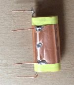
and trimmed the tin foil. Same IAR WONDER-CAP 8.0 uF 200V capacitor.
Hi Mark
If you check using the two hum detection methods shown a few posts back.
http://www.diyaudio.com/forums/loun...ch-preamplifier-part-ii-9180.html#post5045872
and you notice no difference, then these caps are built somehow like Ed says (not prone to hum pick-up)
In a few circuit applications, one could also use copper foil or tin and solder a wire to it and ground it... for a shield.
Right Richard
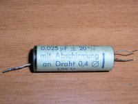
I have met such three-lead caps in RF circuits of old German radios. In one case, I had to improvise

George
Attachments
I'm listening to my Boulders right now. So nice ...
John, I now officially hate you!
When people think rocks talk to them you should worry!
You might need yo rethink that. Many rocks make more sense than some posts here. (Possibly including this one.)
If you are referring to your phono circuit, I realised that.
I was just asking a more general question.
Patrick
I also meant the standard A/D drivers and many xDSL drivers, the common mode is actively driven. I still can't see servoing the common mode to DC 0 and letting the signal common mode through.
You might need yo rethink that. Many rocks make more sense than some posts here. (Possibly including this one.)
"It Is Better to Keep Quiet and Be Thought a Fool Than to Speak and Remove All Doubt."
(I'm not accusing you at all, Ed; this is all self-indictment.
)Like this?
https://www.thefreelibrary.com/Son+of+Ampzilla+2000+Circuit+and+Measurement+Review-a0133864374
-RM
https://www.thefreelibrary.com/Son+of+Ampzilla+2000+Circuit+and+Measurement+Review-a0133864374
-RM
Last edited:
Interesting terminology highjack in that article: Spread Spectrum Design. Spread Spectrum is a term from RF and comms designs. It means that the frequency in the communications system is spread over a specific frequency band and thus not constant. The idea is to prevent eavesdropping and jamming by an adversary, and the technology originates (where else) from military research. Another term is 'frequency hopping'.
In the article linked to above it appears that they use the term to indicate a 2- or 3-way speaker system, where as usually each speaker reproduces a specific frequency range. I can imagine that the term Spread Spectrum Design for a multiway speaker gives a marketing advantage in the highly competitive market. I just hope we are not heading into another confusion like with the dual different use of the original the term 'current feedback'!
Jan
Spread spectrum also used for some SMPS designs, to create lower level but braoders spectrum of noise. Funnily we did some spread spectrum RF stuff and we could get away with more jitter than the average audiophile considers terminal
The use of the term that article is a bit confusing.
The use of the term that article is a bit confusing.
Spread spectrum also used for some SMPS designs, to create lower level but braoders spectrum of noise. Funnily we did some spread spectrum RF stuff and we could get away with more jitter than the average audiophile considers terminal
The use of the term in that article is a bit confusing.
Yes in SMPS it makes sense, I agree.
The confusion only exists with people that know the original term. Joe Audiocustomer most probably never has heard the term before and will have the idea he is looking at a Breakthrough. Hence the marketing advantage.
Jan
- Status
- Not open for further replies.
- Home
- Member Areas
- The Lounge
- John Curl's Blowtorch preamplifier part II