The Royal "we"? Then June 7, 1977 applies.
BBC ON THIS DAY | 7 | 1977: Queen celebrates Silver Jubilee
Otherwise I'm so beyond confused I can't keep track of the exchange. Well, except the *wonderful* level of animosity from all parties. :/
Anyone can suggest a fully differential (input & output) opamp with JFET input
Not ideal, but 2xINA110 will do nice for audio.
BBC ON THIS DAY | 7 | 1977: Queen celebrates Silver Jubilee
Otherwise I'm so beyond confused I can't keep track of the exchange. Well, except the *wonderful* level of animosity from all parties. :/
https://www.theguardian.com/music/2012/apr/29/sex-pistols-queen-jubilee-boat
The parade was two days later.
God save the queen
The f...
They made you a moron
A potential H bomb
Establishment moronic behaviour.... https://images.991.com/large_image/Sex+Pistols+Jubilee-356361.jpg
Low technology talk.
Check where the outer foil of a cap is to be connected in low noise circuits.
Check by
George
The way I tell which is the outside foil comes from cap mfr when I asked them --- is ---
If you can measure capacitance...... place the tubular film cap inside a metal tube. The C from one lead to the metal tube will be highest with the lead which is attached to the out side foil.
Done. Simple and works without a lot of circuitry (not counting the cap tester).
THx-RNMarsh
Last edited:
Not ideal, but 2xINA110 will do nice for audio.
Too noisy especially at low gains. 5nv at a gain of 5 should be achievable with a 389 pair and the THAT 1580, it does require some DIY work though.
It does remove the output common mode which is a separate issue. I have a solution for that too, I think PMA posted a version it awhile back (a simple FET in-amp with only a FET pair and a dual op-amp). Connect two of those like that late figure on the BB datasheet (I wonder where that came from).
http://www.waynekirkwood.com/images..._Noise_Wurcer_Kitchin_EDN_October_13_1982.pdf
Last edited:
I meant something like OPA1632, but with JFETs at the input
What would a jfet input opa1632 bring to the table, performance wise? I can't figure out any advantage, except perhaps a better behaviour with ingress EMI, and even that would be at best marginal.
If you have a fully differential amp like the BT, and you want to use a differential servo, then a JFET-OPA1632 would fit the bill, not ?
No, you will need CM servo as well
I used my AP and built a shaker table out of a JBL pro woofer. Used an accelerometer to verify shake, rattle and roll.
Stacked plate capacitors could be oriented so the microphonics were minimized. Electrolytics had minimal problems. The physically larger version of many capacitors of the same manufacturer and type also were better.
No real surprises.
Now for the microphone preamps used outside small rooms, a transformer input is my first choice. But the center tapped transformer does not work with Earthworks or other differential pair style phantom power microphones as the current draw is not balanced.
I did some tests a few weeks ago and posted the results up here somewhere. Smacked the hell out of the caps and the 110k bias resistors. I think high value R's might be a bigger problem than electrolytic caps - still to complete the tests to verify though.
Nice practical test set up BTW.
The way I tell which is the outside foil comes from cap mfr when I asked them --- is ---
If you can measure capacitance...... place the tubular film cap inside a metal tube. The C from one lead to the metal tube will be highest with the lead which is attached to the out side foil.
Done. Simple and works without a lot of circuitry (not counting the cap tester).
THx-RNMarsh
an example... to find the ground side or outside foil-lead -----get some tin/alum-foil from the kitchen and wrap around body of cap/DUT:
I'll let the pictures do the talking.


THx-RNMarsh
Last edited:
QUOTE=gpapag;5046427]Thank you Richard
George[/QUOTE]

If one is careful to zero out the c between leads and not move the leads more than a fraction of an inch during tests, there is a distinct different. Notice, my meter has the zero feature. And don't have the foil go over/past the cap ends.
-Richard
George[/QUOTE]

If one is careful to zero out the c between leads and not move the leads more than a fraction of an inch during tests, there is a distinct different. Notice, my meter has the zero feature. And don't have the foil go over/past the cap ends.
-Richard
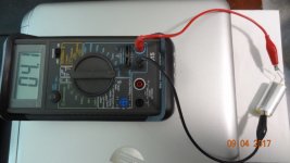
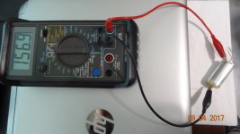
8.0 uF 200V WONDER-CAP purchased from J. Peter Moncrieff / IAR
183 pF: tinfoil to cap left lead
191 pF: tinfoil to cap right lead
photo attached
If you are careful in c measurement, it would be the right lead which is the outer foil.
In a few circuit applications, one could also use copper foil or tin and solder a wire to it and ground it... for a shield.
-Richard
Last edited:
Dug out the Agilent LCR meter with zeroing feature (they call it "Null" , it's the keypad at bottom right) and trimmed the tin foil. Same IAR WONDER-CAP 8.0 uF 200V capacitor.
260.1 pF foil to cap right
264.2 pF foil to cap left
images below. BTW waving the leads around a few inches, changed the displayed capacitance by 1-4 pF.
260.1 pF foil to cap right
264.2 pF foil to cap left
images below. BTW waving the leads around a few inches, changed the displayed capacitance by 1-4 pF.
Attachments
- Status
- Not open for further replies.
- Home
- Member Areas
- The Lounge
- John Curl's Blowtorch preamplifier part II


