Usually, the problem is with the drivers supplied by sound card manufacturers.
Of course just one example I had, under XP CoolEdit supported ASIO drivers but now it doesn't (WIN10) while CoolEdit itself runs fine and yes certainly no point in pursuing why anymore. Though such things get frustrating.
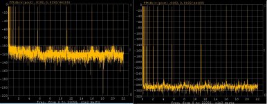
On the multi-tone issue:
I had a few moments to run a purely numerical simulation on one of the AP files that Jan posted. I used the 44100 sampling frequency. The missing information is easily derived from what is given. From any of the numbers you can derive the frequency of bin 1 which gives the length in time of the record so in this case the FFT length is 8192 and the bin frequencies are n*(44100/8192). They used 22 bins here. I used a simple POLY vcvs to add a fixed set of distortion orders. By the 5th order there was only one empty bin left and I have no idea how to interpret the distortion floor in any way but less is better. If you restrict things to 2nd and 3rd order only there are many empty bins.
The second figure is the input (poly = 1*input) and the first is the output (input*a polynomial with all orders up to 5 with small distortion coefficients).
EDIT - I would surmise from this that the concept of harmonic progression is somewhat lost here.
Attachments
Last edited:
The meter reports on that total field storage, and reports as well on what it sees as energy loss. It does not care if the loss is at drive frequency or any harmonics of drive, it just integrates the total energy that does not return to the meter.
In that regard, the meter will not provide an independent measure of proximity losses which are at double frequency (the primary loss mechanism when resistance is modulated by the absolute value of the rate of magfield change). So it will not distinguish internal crowding loss within an inductor winding from external eddy losses of nearby conductive objects.
John
Nice explanations. IYO, as an educated guess perhaps, what freq are we dealing with for skin effect only? From your charts and graphs and others it appears to be between 1K and 10KHz.
THx-RNMarsh
Nice explanations. IYO, as an educated guess perhaps, what freq are we dealing with for skin effect only? From your charts and graphs and others it appears to be between 1K and 10KHz.
THx-RNMarsh
For single wires, I don't consider skinning of the current as an issue in the audio band, even out to 100Khz. If you examine the bessel solution at 1.5mm wire and 20 Khz, it is clear that there is not much going on.
If I try to run 20 kiloamps in a round conductor, then I'd worry about skin at 60 hz. Otherwise, it isn't meaningful. The exponential approximation is useful in that regard, but remember that it overstates the skinning significantly in the audio band, if one designs to it, one will overkill by a factor of 3 to 5 (in general), and fret about values which are off by the same factor..
However, you said my charts and graphs. We were just discussing proximity effects on an air core inductor with hundreds of turns and proximity effect. That is NOT the same as skin effect on a wire, as it is an enhanced field on the order of 4 or 5 orders of magnitude greater than a single conductor.
Those specific graphs and measurements are to show everybody how an inductor goes "bad" at audio frequencies due to proximity based losses, and how it can be ruined response wise just by attaching it to a crossover PC board where the backside of the board has a full pour of copper.
Ideally, a crossover should have litz air core inductors and they cannot be put against clad nor any conductive surface of significant cross section, as that will both lower inductance and increase resistive losses.
As I recall, you measure inductors for Q, which is also a very good way to characterize the losses.
John
If I try to run 20 kiloamps in a round conductor, then I'd worry about skin at 60 hz. Otherwise, it isn't meaningful. The exponential approximation is useful in that regard, but remember that it overstates the skinning significantly in the audio band, if one designs to it, one will overkill by a factor of 3 to 5 (in general), and fret about values which are off by the same factor..
Ideally, a crossover should have litz air core inductors and they cannot be put against clad nor any conductive surface of significant cross section, as that will both lower inductance and increase resistive losses.
As I recall, you measure inductors for Q, which is also a very good way to characterize the losses.
John
I havent been too concerned about the absolute values involved just at what freq it started. Though the level of atten is typically low due to these effects, they start in audio range. In typical home application it is a fraction of a dB at most. BUT --
In power amp design and its pcb and wiring quite high amperage can be found. In 'normal' PA use there are tens of amp peaks. In commercial systems, we have Very high power amps and longer cable runs also. The amps I have for example can produce Huge power peaks (2500W each channel). Of course we would not use those amps..... or would we? The JBL M2 Reference Monitor uses them.
If I get more than 0.1dB of HF audio atten due to cable losses, including skin effect, then I would want to reduce it.
Thanks for your clarity and explanations of the physics involved.
THx-RNMarsh
Last edited:
The top 40 and top 100 throw away music recordings are made with DAW (Pro-Tools typically) and 'sound card' like products. With this for source, its the best they offer the consumer. Fortunately for me, I dont listen to a lot of the top 100 tunes.
Has anyone measured distortion(s) of top 100 throw away songs? they dont sound very good... is it all just what the producer/musician liked and not the gear/use?
The various ADC/DAC get tested regularly..... But just how trashed is this 'music' process?
On second thought... guess it doesnt matter.
THx-RNMarsh
Last edited:
Has anyone measured distortion(s) of top 100 throw away songs? The various ADC/DAC get tested regulary..... But just how trashed is this 'music' process? On second thought... guess it doesnt matter.
THx-RNMarsh
It matters to a lot of people. Some distortion sounds good to many people, and other distortion sounds awful. For example, like many people I like distorted electric guitars. There is/was a band called Chickenfoot, with Joe Satriani on guitar. They made a CD which sounds horrible, the mp3s of it actually sound better than the CD, presumably because the lossy mp3 encoder discarded some of the distortion as perceptually unneeded. The CD sounds to me like it may have been recorded on a very early Pro Tools system or similar. Anyway, I like the funk groove of "Soap on a Rope," but the distortion on the CD ruins it.
On the multi-tone issue:
I had a few moments to run a purely numerical simulation on one of the AP files that Jan posted. I used the 44100 sampling frequency. The missing information is easily derived from what is given. From any of the numbers you can derive the frequency of bin 1 which gives the length in time of the record so in this case the FFT length is 8192 and the bin frequencies are n*(44100/8192). They used 22 bins here. I used a simple POLY vcvs to add a fixed set of distortion orders. By the 5th order there was only one empty bin left and I have no idea how to interpret the distortion floor in any way but less is better. If you restrict things to 2nd and 3rd order only there are many empty bins.
The second figure is the input (poly = 1*input) and the first is the output (input*a polynomial with all orders up to 5 with small distortion coefficients).
EDIT - I would surmise from this that the concept of harmonic progression is somewhat lost here.
Scott I am pretty sure there's more to it than the file I posted. I remember that the algorithm also fiddled the relative levels, phase shifts and crest factor. I wish I could find the stuff!
Jan
Scott I am pretty sure there's more to it than the file I posted. I remember that the algorithm also fiddled the relative levels, phase shifts and crest factor. I wish I could find the stuff!
Jan
That shouldn't matter the numbers given mentioned that the crest factor and equal levels given were the intended ones. Yes you can rotate the phases to minimize and maximize the crest factor over a certain range. The minimum crest factor is a neat math problem the max is obvious.
I've had good luck when I can get a card to work full duplex in ASIO. ARTA for instance will play/record in perfect sync all day long with several very cheap USB devices. CoolEdit 2000 worked great under XP but now I can't get two instances to play/record together anymore after Win7.
Scott, I think that might've been a lucky choice of usb soundcards. The problem when it occurs is hardware, not with drivers or software. The TI PCM29xx USB audio chips were the most frustrating examples, as they were used in a number of inexpensive USB soundcards by Behringer, iMic, and some others that were otherwise nice and basic (no silly nonsense features like the soundblaster type devices always wanted to include, that made use for measurements difficult or impossible). Record and play sampling at the same nominal rates can walk away from each other over even just a few seconds, but since it is somewhat up to chance match between crystals in the usb device and the host computer, it can seem ok for some times.
edit: not saying that all usb cards have this problem, btw. Some of them, such as the ESI/Maya or M-Audio devices used a common clock and worked fine. Of course Windows sample rate conversion (if it is used for some reason like the system thinks it has to for combining your audio stream with all the system alert sounds) can also cause issues.
Last edited:
It's just what you get used to. I generally don't use any musician oriented features I normally only do one track and use it as a measurement instrument on amplifiers etc. If I google, "reaper ASIO" I see the usual flock of folks having issues, that would be me. Right now I'm moving to ARTA and Python.
We just went through one of these issues a few weeks ago. Lots of people didn't realize that there is no way to get Audacity to record 24 bits, no warning just 8 "0" LSB's (no ASIO support) .
I PM'd you!
Although Harwood wrote about "on-axis response" i think it is clear that he is describing effects from the "on-listening-axis response" .
I am not sure, but afair the general praxis in the BBC rooms was to place the speakers backside parallel to the front wall without toe in.
So you are now putting words into his mouth now? Or are you just changing your position? I think if he had meant power response he would have said so.
The great thing about the BBC is that you don't have to recall, you can look it up.
Type D in Studio B6
Or, if you have some reading time. http://downloads.bbc.co.uk/rd/pubs/reports/1995-04.pdf which has some fascinating analysis of the problems with control room design. It is dated after the BBC stopped designing new monitors in house, but refers to refurbishment of control rooms that had been there for some decades. And in the pictures and diagrams the speakers are clearly toe'd in.
Of course there is someone who can put all these questions to bed, and that is Alan Shaw as he extensively interviewed DH before his death. But as I said before I tire of this particular line as the world believes in the BBC dip and that we all listen to polite speakers whilst sipping our earl grey and having scones. Me? I have one pair of speakers from the east coast USA and one from the west. No idea what that labels me as, other than needing more speakers!
What does still interest me is what the power response considerations are for nearfield listening and if they vary from farfield requirements.
Some of them, such as the ESI/Maya or M-Audio devices used a common clock and worked fine. Of course Windows sample rate conversion (if it is used for some reason like the system thinks it has to for combining your audio stream with all the system alert sounds) can also cause issues.
I checked EMU, M-Audio (no supported drivers anymore), and now I found the Xonar U5 and ARTA work in lock step just fine. At some level I'm not doing anything sophisticated but I am looking for certain exact engineering requirements. Maybe a bunch of hidden SRC works for the OS and is not audible but it doesn't fly computationally.
It's bizarre in a way, the hardware is so beyond being able to do 2 channels of 24/96 audio in/out simultaneously it's not funny.
EDIT - BTW I'm perfectly happy to do bridge or Cordell distortion magnification things, I don't see any point in brute force measurements. So the U5 is -95db and I can boost that 40db with passives so I'm happy.
Last edited:
The great thing about the BBC is that you don't have to recall, you can look it up.
I find this side discussion amusing. About 25yr. ago I won a raffle for a pair of bookshelf speakers with a given budget. I had 4 young kids and was in the no life no interests period so I went to a hi-end store in NH and asked them to put up 3 samples B&W, JBL, and Snell. Even after years of paying no attention it took seconds to point out the "British" sound the west coast sound and the Boston sound (AR, KLH, Boston Acoustics) each very distinct and re-callable after 20yr. I picked the Snell apparently one of the last speakers Peter Snell actually designed.
Actually, effects of wires do NOT occur in the audio range. Reading 1 kHz or 10 kHz measurements of an inductor and extending that thought to wires is not correct. It is quite misleading in fact. To run that direction in a random fashion does not aid in our understanding of the problem, it confuses it.I havent been too concerned about the absolute values involved just at what freq it started. Though the level of atten is typically low due to these effects, they start in audio range. In typical home application it is a fraction of a dB at most. BUT --
In power amp design and its pcb and wiring quite high amperage can be found. In 'normal' PA use there are tens of amp peaks. In commercial systems, we have Very high power amps and longer cable runs also. The amps I have for example can produce Huge power peaks (2500W each channel). Of course we would not use those amps..... or would we? The JBL M2 Reference Monitor uses them.
If I get more than 0.1dB of HF audio atten due to cable losses, including skin effect, then I would want to reduce it.
Thanks for your clarity and explanations of the physics involved.
THx-RNMarsh
That said, there are many problems inherent in the design of amplifiers with low impedance loops that "ignore" the rules we learned with vacuum tubes...things like star grounds. Ground loops and stray currents are very difficult to determine, understand, and manage.
There is much to teach, even more to learn. I hope to do some of both before I go.
Cheers,
John
I find this side discussion amusing. About 25yr. ago I won a raffle for a pair of bookshelf speakers with a given budget. I had 4 young kids and was in the no life no interests period so I went to a hi-end store in NH and asked them to put up 3 samples B&W, JBL, and Snell. Even after years of paying no attention it took seconds to point out the "British" sound the west coast sound and the Boston sound (AR, KLH, Boston Acoustics) each very distinct and re-callable after 20yr. I picked the Snell apparently one of the last speakers Peter Snell actually designed.
What is more interesting is that when measured they all probably had very similar on axis frequency response. Kind of amusing how smaller microphone capsules and loudspeaker turntables have opened up the measurement capabilities and improved the results.
In studio monitors some folks found when they used the smaller capsule microphones that correcting the high frequency response was not met with acceptance. The folks using and buying them were so used to the older designs the new ones were considered too harsh. So it took a bit of new models with slowly improving HF response to meet the market expectations.
Actually, effects of wires do NOT occur in the audio range. Reading 1 kHz or 10 kHz measurements of an inductor and extending that thought to wires is not correct. It is quite misleading in fact. To run that direction in a random fashion does not aid in our understanding of the problem, it confuses it.
That said, there are many problems inherent in the design of amplifiers with low impedance loops that "ignore" the rules we learned with vacuum tubes...things like star grounds. Ground loops and stray currents are very difficult to determine, understand, and manage.
There is much to teach, even more to learn. I hope to do some of both before I go.
Cheers,
John
I am not sure where the wire (only) comes from but that isnt my only appl.
I have done a lot of inductor measurements also... for passive x-over filters.
Most of what is available vary with freq. yet, they are all spec'd for L at 1KHz only. And for a high Q and air core, it gets impractically large in diameter, as I recall.
Moving to bi/tri-amped.
THx-RNMarsh
Which is all good. But to assume that skinning of a wire is significant at audio frequencies is a stretch of 4 to 6 orders of magnitude.I am not sure where the wire (only) comes from but that isnt my only appl.
I have done a lot of inductor measurements also... for passive x-over filters.
Most of what is available vary with freq. yet, they are all spec'd for L at 1KHz only. And for a high Q and air core, it gets impractically large in diameter, as I recall.
Moving to bi/tri-amped.
THx-RNMarsh
I am somewhat "picky" (the "a" word won't clear the filters), but 3 to 4 exponents below what I can measure is pretty low.
Inductors,that's a different horse.
Bi wire, now that' an interesting discussion. Bi amp, boring..
John
- Status
- Not open for further replies.
- Home
- Member Areas
- The Lounge
- John Curl's Blowtorch preamplifier part II