Yes. That is what I would do (and have done). A good 1/4 inch will be flat for all uses of freq measurement apps.
The one inch is too limited.
THx-RNMarsh
Shh, you are giving away too many secrets. I have half a dozen 1/4" microphones for field use including some with calibrated transmitters/receivers.
One time I dropped one in a stadium, as the cord was still attached it landed capsule first and destroyed it. Fortunately it was one of the cheaper ones about $700 as I recall.
Yes you are using the correct terms, but the advertising has changed them a bit as they got confusing to some folks.
There there was the guy at the sound contractors show who picked up a sound level meter at the Bruel and Kjaer booth and asked what it was! (True story.)
RNM I know you like to collect useful test equipment and certainly have more than I do for the electrical measurements, but I really do need a good assortment of microphones to do my work.
Yesterday and today has been a bit exciting. I shipped two mondo loudspeakers to Seattle packed hanging inside their crates. The arrived upside down unwrapped on pallets badly scratched up. So JJ did me a favor and swept tested them. The drivers are all apparently OK but they did smash the boxes on the back enclosing the Zobel networks. However impedance readings show everything is working. So for a bit more than a kilobuck replacement hardware will be there tomorrow. (Labor extra.) Should have started hanging them on Tuesday, now looks like Friday. Anyone care to guess the chance of them postponing the start of the NFL season?
Total replacement loudspeakers would be a 12 week item. Oh yeah a bit under 15K each.
Gonna be interesting to see how the shipping damage claim works out.
The effect was quite large for a couple of 2SK222's that I tried .304V and .253V Vp when fit from 100uA to Idss to the standard square law model and .482V and .435V Vgs at 50nA.
Yep the printouts from the scribelane test structure in volume production CMOS DRAMs, routinely include three different VT's (measured on the same transistor). VTlinear, VTsat, and VT1uA/um.
VTlinear was the VGS intercept of the max slope tangent of IDS vs VGS at very low drain voltage (VDS=0.05), so low as to guarantee linear region operation.
VTsat was the VGS intercept of the max slope tangent of sqrt(IDS) vs VGS for a diode connected device. This guarantees saturation region operation. By setting VDS=VGS rather than VDS=A_Big_Constant, the diode connection (mostly) avoided drain induced barrier lowering.
VT1uA/um was the value of VGS of a diode connected device, which gave 1uA of IDS per um of drawn channel width.
Why did we have 3 different definitions of VT and three different ways to measure it (and 3 measured values that differed from one another by 0.25 volts)? Different workgroups had their own, different favorites. Really.
Yep the printouts from the scribelane test structure in volume production CMOS DRAMs, routinely include three different VT's (measured on the same transistor). VTlinear, VTsat, and VT1uA/um.
Since JFET's are depletion mode I would think the analogy between VT and VP would break down. In fact going to 100pA (still well below the leakage current) the VP became .770 V a useless number at any normal operating current or any useful condition. In fact for a JFET taking the VP at 10nA and Idss at Vgs = 0 yields at totally wrong number for beta the transconductance parameter. JFET's have always been a fringe device what manufacturers do on their data sheets can be stupid or wrong, authority to be questioned.
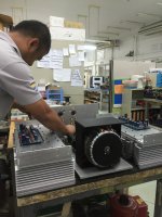
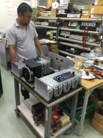
The JBL M2 has left the shipping dock -- I need two of these 2-channel amps.... making progress:
My tech support is via Magnet Techology, Bangkok, Thailand.
Suitably uber High End audiophile system.
View attachment 558544
View attachment 558543
RNM
Still there is no the drivers heat sink mounted, how thy are going to instal it if the board and the output mosfet are already fixed to the main heat sink??
The JBL M2 has left the shipping dock -- I need two of these 2-channel amps.... making progress:
My tech support is via Magnet Techology, Bangkok, Thailand.
RNM
It kills me that you're using less than good input cap config. I'd still like to hear them.
Yes the input cap doesn't look liie a film and foil Multicap. Very nice looking amp otherwise. Any input AC filtering, soft recovery diodes, CRC filtering, front end regulation?
Planning to upgrade the passive portion of the M2 crossover?
I never heard my latest electrostatic speakers stock when I bought them, i replaced the Solen caps with film and foil MIT (about 80 uf a side) the day they arrived. Our work shop has old school 70's JBL systems that use MIT film and foil caps on the 4 of 2441/2395 yard wide lens and 2405 tweeters. Nice in 3000 sq feet.
Last edited:
Lol, relax Dadod your child will be fine.....what you see is the trial fit stage.Still there is no the drivers heat sink mounted, how thy are going to instal it if the board and the output mosfet are already fixed to the main heat sink??
It's going to look impressively industrial, and I would be proud to fit a perspex top cover, especially nice work.
What's the estimated output power, idle power and total power consumption of this monster ?.
Dan.
Last edited:
Maybe the mfr has reluctantly put the number on the datasheet which the Big Important Customer demanded? If the customer wants to use the device as an analog switch for scrawny signals, perhaps "Tell me what I must do to guarantee this thing is shut off, Off, OFF the f-word OFF" is best answered by Vgs@1nA , could it be so?JFET's have always been a fringe device what manufacturers do on their data sheets can be stupid or wrong, authority to be questioned.
I see that NXP's datasheet for BF862 measures VGSoff at 1000 nA, while Toshiba's datasheet for 2SK170 measures it at 100 nA. Yet neither of these JFETs is ever sold as, or purchased as, an analog switch. Hmmm.
If and when I ever need to extract model parameters for JFETs in SPICE, I too may be horrified by the numerical value of the pinchoff model parameter that happens to give the lowest sum of squared errors.
Yes the input cap doesn't look liie a film and foil Multicap. Very nice looking amp otherwise. Any input AC filtering, soft recovery diodes, CRC filtering, front end regulation?
Planning to upgrade the passive portion of the M2 crossover?
I never heard my latest electrostatic speakers stock when I bought them, i replaced the Solen caps with film and foil MIT (about 80 uf a side) the day they arrived. Our work shop has old school 70's JBL systems that use MIT film and foil caps on the 4 of 2441/2395 yard wide lens and 2405 tweeters. Nice in 3000 sq feet.
It will be a better cap. However this is ac coupled.... it can be dc coupled because of the dc servo. You can go to Damir's forum and see the design there. Film and Foil is the Only type which ought to be used... never metallized for speakers. The MIT sourced cap is the same as any sourced MultiCap or if bought directly from manufacturer (large quantity). I share the patent with mfr on the cap design. It is still unique because it required a special made cap machine to make them.
But I plan to use DSP for the cross-over design and two of Damir's amp (bi-amp).
THx-RNMarsh
The same chip in the 2SK170 was in the 2SK364, which is characterized for analog switching. I swept up about a thousand of them when Harman was shutting a program down many years ago.Maybe the mfr has reluctantly put the number on the datasheet which the Big Important Customer demanded? If the customer wants to use the device as an analog switch for scrawny signals, perhaps "Tell me what I must do to guarantee this thing is shut off, Off, OFF the f-word OFF" is best answered by Vgs@1nA , could it be so?
I see that NXP's datasheet for BF862 measures VGSoff at 1000 nA, while Toshiba's datasheet for 2SK170 measures it at 100 nA. Yet neither of these JFETs is ever sold as, or purchased as, an analog switch. Hmmm.
If and when I ever need to extract model parameters for JFETs in SPICE, I too may be horrified by the numerical value of the pinchoff model parameter that happens to give the lowest sum of squared errors.
The JBL M2 has left the shipping dock -- I need two of these 2-channel amps.... making progress
Wow, a PCB layout revision, with the output coil still on the PCB
Don't you love it when (simulated) <10ppm distortions are claimed, then the hyped discussions about ultra low THD measurement, only to have the implementation ruined it by at least an order of magnitude (magnetic induction effects, see the Cherry and Self work).
The final distortion results in this implementation could be actually worse than a standard Lin topology, correctly designed and built. But who cares anyway, it won't be audible and, besides, it's a CFA, which is known to be the best thing since sliced bread.
Otherwise, a true DIY work
 .
.I think Richard measured the amp as is and found it was a great performer. As long as you orient the coils correctly, the magnetic induction issues are quite manageable.
I'm talking about a finished amp, not about a testbench spread. Results could be dramatically different.
Not as long it's on the PCB. Take a look on how the Halcro DM88 installs the output inductor; it's placed in a separate compartment of the massive metal enclosure. Care to guess why?
Last edited:
I think Richard measured the amp as is and found it was a great performer. As long as you orient the coils correctly, the magnetic induction issues are quite manageable.
There is direct output before the coil on that PCB, so it's simple not to install the coil on the PCB, but somewere close to the spekare output connectors.
- Status
- Not open for further replies.
- Home
- Member Areas
- The Lounge
- John Curl's Blowtorch preamplifier part II

