It very much illustrate the mismatch. Time values would have been appropriate however.I only posted the image because I think it nicely illustrates that loudspeaker cable often does not match the intended load. It was for fun not serious study.
This is where you fall flat.No actual values are shown because it is unlikely anyone has a loudspeaker with a flat impedance
That effect is absolutely dependent on the load impedance with respect to the line. Because the load has a frequency dependent impedance, that plot will vary (return pulse magnitude) with frequency. As such, you can see how the system response is load dependent.
The step response test I call for, with the varying load, can characterize the entire system. It's not a difficult test.
I will not show data on my current cable design as it is still in flux. I did have a bit of bother explaining what characteristics were required to get quotes on a sample run. They were more concerned with colors than with twist! Same issues trying to get stranding right.
Twist is a no-brainer, they can alter that at whim. Color, sometimes the exact color can be a problem. Low smoke zero halogen tray rated UL listed, now that can be a problem....
Now if you want to discuss this privately, as I think you are the only one here who has pulled a bit of cable and understands the hidden issues, that is fine.
I am confident (perhaps erroneously so) that no matter what you require in your wire, I've already been there. (do not burst my bubble.
Seriously... If you have any questions that you think I might be of help on, do not hesitate to ask me, you are always welcome. I've no desire to steal the work of others.
John
50mA at 100K is 5KV. So a fuse will not work. But a 50mA fuse would produce .05% distortion. A 250mA fuse would meet your resistance requirement.
Yes good point, the 50mA is the limit when something breaks but at that point I'm not worrying about THD anymore.
Jan
Gents,
While you relax and think about your next move, can I wiggle in a question?
I am contemplating the use of a fuse to protect the input of a high dynamic range test system. Because the fuse is in series with the input, the fuse resistance variation must remain below a certain value so as not to cause distortion.
But for the life of me I cannot find any info about how a fuse resistance varies with the current it carries (which is in normal operation far below its fusing current anyway).
Anybody has or knows a source of such info?
Jan
PS Fully agree with Jneutron last post. For the record.
And, does it matter one jot unless you also take the same approach with the main fuses, and the power company fuse?
And, re - JN -- ditto!
This is where you fall flat.
That effect is absolutely dependent on the load impedance with respect to the line. Because the load has a frequency dependent impedance, that plot will vary (return pulse magnitude) with frequency. As such, you can see how the system response is load dependent.
I am confident (perhaps erroneously so) that no matter what you require in your wire, I've already been there. (do not burst my bubble.)
John
JN,
Why make agreeing sound like a disagreement.... We both know that almost all loudspeakers have significant impedance variations and that a simple resistor loading does not show that effect.
As to bursting your bubble. I'll bet you know what a 1/4 wavelength antenna is. Ever put one up 1/2 mile from a 50 KW AM station? Seems to save money some folks want to string wire without conduit! I'll bet you can pick up on those issues. (You know smoking amplifiers, funny noises etc.)
Why make agreeing sound like a disagreement.... We both know that almost all loudspeakers have significant impedance variations and that a simple resistor loading does not show that effect.
You've missed my point.
For long lines with a non matched frequency dependent load, phase coherence is lost. TDR can show simply the reflection change, but a step function will show much more. It shows the settling time of the system and it's dependence on the load impedance.
Knowing the settling time, you can back into the time shift vs frequency vs load impedance.
For best fidelity at the load, you have to minimize that. Otherwise, temporal coherence is lost.
John
And, does it matter one jot unless you also take the same approach with the main fuses, and the power company fuse?
And, re - JN -- ditto!
Not at all. Not in this application.
Read my post.
Jan
Last edited:
Did you specify a minimum bend radius?I am awaiting delivery of the cable that I had made of 12 gauge twisted pairs with .011 of polypropylene insulation.
John
Did you specify a minimum bend radius?
John
6"
you know what a 1/4 wavelength antenna is. Ever put one up 1/2 mile from a 50 KW AM station? Seems to save money some folks want to string wire without conduit!
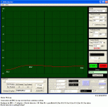
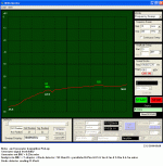
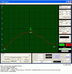
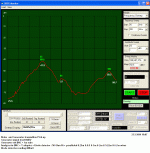
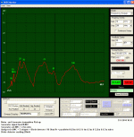
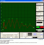
In my workshop, a 10kHz to 200MHz sweep generator (Ro: 50 Ohm) drives a single wire antenna of a varying length with a 1Vrms signal.
At a small fixed distance there are six single wires (0.25m, 0.5m, 1m, 2m, 5.22m, 6.7m) connected in parallel at the input of an analyser which is synchronised to the sweep generator. It’s 1MOhm/20pF input is 50 Ohm terminated. A 50 Ohm broadband diode detector is connected in parallel to it.
The variable in the attached screenshots is the length of the transmitting antenna.
Green numbers show frequency (MHz), white numbers show amplitude (dBV)
Horiz axis is linear 20MHz/div.
First screenshot is the ambient RF noise in my workshop at the basement level.
This noise varies with time and day. It can reach –55dBV on a noisy day.
One floor up and the RF noise goes up by 6 to 9 dB.
I am 5km away (line of sight) from a location with many TV and FM transmitting station antennas and 4km from an air force surveillance radar.
George
Attachments
Not at all. Not in this application.
Read my post.
Jan
Apologies -- in amongst the discussion on power fuses I misread your "input" as meaning power in, not signal in.....
Anyone who remembers the very first Outer Limits with the alien sucked in when the DJ turns up the power will recognize the tower directly over my house, within about 100 meters or so. Lots of antennae and different wavelengths to deal with. I think you have it easy George, I'm right in the cone of that antennae, 50kw of radio station and microwave to boot with a bunch of what look like repeaters for radio transmission, a veritable jungle of RF. I don't worry much about cell phone transmission next to my head compared to this RF density!
A friend of mine, who used to build pirate radio transmitters was once asked to look at a problem with someones tv. They were Line of sight to crystal palace transmitter in london which was around 1MW ERP in the analog days and for some reason had the sort of yagi you would use in the boonies. He measured 17V at the TV input.
The effect of the shield! Try the coax calculator.
Gents,
While you relax and think about your next move, can I wiggle in a question?
I am contemplating the use of a fuse to protect the input of a high dynamic range test system. Because the fuse is in series with the input, the fuse resistance variation must remain below a certain value so as not to cause distortion.
But for the life of me I cannot find any info about how a fuse resistance varies with the current it carries (which is in normal operation far below its fusing current anyway).
Anybody has or knows a source of such info?
Jan
PS Fully agree with Jneutron last post. For the record.
Use a slow blow fuse for low distortion vs current. But, then protection may not be fast enough to protect sensitive input/hardware. However, fuses are really to prevent fires.
There are faster, low distortion ways.... maybe protection like A-P uses would help you best.
I thought I had blown one of the A-P inputs a month ago when I accidentally put +15vdc on the input... in dc coupled mode. Wouldnt measure distortion. Input must be blown.
After ordering new pair of matched input modules and new protection devices...... going thru thier check list... all seemed OK. I tried it again and it is still working fine. It had just latched up. Now I have a couple rare matched input modules lying around. A-P approach doesnt add distortion and is fast acting.
THx-RNMarsh
Last edited:
WOW a little front end overload I take it ! Well the signal to noise should have been good. .A friend of mine, who used to build pirate radio transmitters was once asked to look at a problem with someones tv. They were Line of sight to crystal palace transmitter in london which was around 1MW ERP in the analog days and for some reason had the sort of yagi you would use in the boonies. He measured 17V at the TV input.
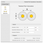
But as mentioned before I am looking at how real cables behave on my size projects. I am awaiting delivery of the cable that I had made of 12 gauge twisted pairs with .011 of polypropylene insulation.
The effect of the shield! Try the coax calculator.
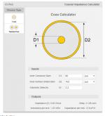
Couldn't find a calculator for shielded twisted pair if that's what you mean.
Dan.
View attachment 551778
Couldn't find a calculator for shielded twisted pair if that's what you mean.
Dan.
There isn't one but the one you used would be a bit more accurate if you calculàted one layer if insulation.
- Status
- Not open for further replies.
- Home
- Member Areas
- The Lounge
- John Curl's Blowtorch preamplifier part II
