Some where I got some of you guys going in the wrong direction with me. Maybe I jumbled pictures with comments.
The additonal LPF at the DAC output that I made cannot have any affect on the creation of the 'Gibb's' ringing.
When I added the filter at the analog output to remove HF, I also saw the Gibb's signal (ringing-like) not at the analog output any more; All removed from entering the PA input.
The end result is a much better output signal. I do not know why that filter was not already at the DAC output of a Mastering machine. I am sure there is a good explanation somewhere.
The analog output is now clean and clear. The PA being used at this time is a Marantz 7025....... I am having built several samples of Damir's (DADOD) wonderful SOTA amp...... a 450v/usec CFA with ultra low distortion at all load and output levels over a very wide bandwidth. I will use it to check any change in distortion and audibles with and without the HF filter. and compare with other VFA of conventional design/performance.
THx-RNMarsh
I read you loud and clear. The only thing I am interested in is to remove any unwanted junk from my CD output, as I believe I have a problem with it which has cost me a burnt out tweeter. No tragedy, I have 3 spare ones, but obviously that's not inexhaustable - nor cheap. And it happened on one occasion when I let an amp rip out, with peaks hitting 70W. That should be the last time such a thing happened in my home.
I have neither the knowledge, nor the incpination to rebuild my entire CD player. If I decide to build my own preamp, the CD input buffer will include a second order filter to deal with ultrasonics. In that respect, I obviously profited from this discussion and my thanks to all for that.
One thing that glares out to me ........ :
You guys need good 'ol analog scopes !

I fear there is a whole generation of scope users who suppose that the grass from inadequate quantization is really part of the signal.
I cut my teeth on old Tek scopes such as the 535, which, although they were not the fastest, did have a wonderfully small spot size. By the 2236, a wonderful instrument, things were faster and it was harder to burn the phosphor, but the trace was noticeably thicker.
I carped years ago about Stereophile's sidebars using DSOs that had lots of ragged tops of square waves. They are better now, but still likely to be misleading for many who have never seen a really clean trace.
What are the rise and fall times of the "before" square wave?
More to the point - what is the frequency of the square wave?
Without studying the user guide for the scope I can convince myself that it is either 1 KHz or 10 KHz. By appearance, it looks much more like a 1 KHz square wave on a traditional CD player, but this particular player is supposed to be weird, and how would one know a priori, how weird?
I fear there is a whole generation of scope users who suppose that the grass from inadequate quantization is really part of the signal.
I cut my teeth on old Tek scopes such as the 535, which, although they were not the fastest, did have a wonderfully small spot size. By the 2236, a wonderful instrument, things were faster and it was harder to burn the phosphor, but the trace was noticeably thicker.
I carped years ago about Stereophile's sidebars using DSOs that had lots of ragged tops of square waves. They are better now, but still likely to be misleading for many who have never seen a really clean trace.
This small portable I used --- isnt as clear as the old crt scopes for sure. but even as the crt types got faster and faster... the noise started to make the trace fuzzy/thicker. I also have a 7905 scope (crt) with an array of specialised plug-ins. But I think my favorite general-purpose bench scope was the 485.
My first job as a kid in electronics was trouble-shooting to the component level and repair and calibrate all TEK products. i did every tube model scope and plug-in and ss scope/plug-ins up thru the 7000 series... then I got a real job.
") Learned a lot, though, from some sharp TEK guys. I still have camera and Poloroid film packs used up to about 6 years ago for the 7905. I also have an older sampling scope ... same BW but build-in disk at least.... HP-54522a. The new color, light weight, portable sampling types though store on removable storage devices and make signal capture and analysis easy with a lot of math functions built-in. The one I used is equiv 300MHz/ 2.5 Gig samples/sec. And, it includes build-in FFT firmware (optional). yes, the trace is a bit fuzzy at times. If it was a crt scope, you would see there is a very small ripple on the square wave trace top.
Learned a lot, though, from some sharp TEK guys. I still have camera and Poloroid film packs used up to about 6 years ago for the 7905. I also have an older sampling scope ... same BW but build-in disk at least.... HP-54522a. The new color, light weight, portable sampling types though store on removable storage devices and make signal capture and analysis easy with a lot of math functions built-in. The one I used is equiv 300MHz/ 2.5 Gig samples/sec. And, it includes build-in FFT firmware (optional). yes, the trace is a bit fuzzy at times. If it was a crt scope, you would see there is a very small ripple on the square wave trace top. THx-RNMarsh
Last edited:
Yes, the 485 was a nice job. I have one sitting on the floor ready for use when I need the additional bandwidth.But I think my favorite general-purpose bench scope was the 485.
THx-RNMarsh
For a hoot read the recent Stereophile review of the latest Audio Note DAC, especially JA's sidebar measurements and comments.
While the article is not on the web, it appears that the sidebar is here:
Imgur: The most awesome images on the Internet
The typical NOS DAC roll-off in the audible range is shown here:

Last edited:
Per screenshots of post #77036, rise and fall times seem to be almost equal.What are the rise and fall times of the "before" square wave?
The ‘before’ as I read it for 10% to 90% is approx. 20us .
The ‘after’ is double of it (it bears also a measurement “Rise 35.45us, Fall 37.55us”).
The frequency is 1kHz (one period is 10 divisions at 100us/div for the ‘before’ trace, 5 divisions at 200us/div for the ‘after trace).
So, for this 1kHz SQRW, by counting the ripples, I would say that the ‘before’ is brickwall LP filtered at approx. 21kHz. Scott has said it already here:
Richard, let me put it this way the scope photo (with "ringing") that you posted has 1kHz plus the first ten odd harmonics ONLY i.e. the 21kHz harmonic is it, nada, nothing above that in the waveform.
George
The last page of my copy includes JA's remark, featuring his customary diplomacy: "Overall, it is difficult to avoid the temptation to describe the Audio Note DAC 2.1x Signature as 'broken'! "While the article is not on the web, it appears that the sidebar is here:
The analog signal is from an analog signal generator.... perfect square wave.
I have it back in my system again and listening to music. I wont do any more work until the second one arrives.
THx-RNMarsh
The answer is right there by standard rule of thumb 35us rise time = 10kHz BW IIRC for any order filter.
http://www.tek.com/components/low-pass-filters
Last edited:
As ‘broken’ as the 4.1 was (is) !.
Which would be, technically speaking pretty broken if we are to believe:
Audio Note CD-4.1x CD player Measurements | Stereophile.com
But what is THD only 50 dB down, and -6 dB @ 20 Hz into a 12 K ohm load among friends? ;-)
Talkative enough, thanks, Richard.Before and after:
Which would be,
Yes Arnold
Technically speaking, broken. Listening impressions, generally enthusiastic (*).
The designers decided to go by ear, thus a very vinyl system-like outcome as bonsai politely implied.
George
(*) except of course for very complex music, not a favourable choice among reviewers.
Whenever I experiment with a new diy loudspeaker, the initial adjustments by ear always provide me with “wow” moments, impressive results with ‘easy’ music. When I start measuring, I see horrible frequency unbalances. And I start correcting. Sniff sniff . "Wow" moments are gone.
George
Per screenshots of post #77036, rise and fall times seem to be almost equal.
The ‘before’ as I read it for 10% to 90% is approx. 20us .
The ‘after’ is double of it (it bears also a measurement “Rise 35.45us, Fall 37.55us”).
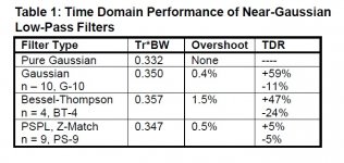
This all fits ~20kHz in first case ~10kHz in second case. Table from reference below shows there is little deviation from tr ~= .35/BW across filters. That is 35usec rise time = 10kHz BW.
http://www.coe.montana.edu/ee/lamer...h_paper_NIappnote_on_gaussian_risetime_bw.pdf
Attachments
I didn't believe that it was possible to make a DAC that does that poorly in common tests.For a hoot read the recent Stereophile review of the latest Audio Note DAC, especially JA's sidebar measurements and comments.
It is not broken, just badly engineered. Not so surprising.
I hope it's expensive.
- Status
- Not open for further replies.
- Home
- Member Areas
- The Lounge
- John Curl's Blowtorch preamplifier part II