Damir, the low impedance feedback is imposed by the parasitic capacitance of the emiter of the input transistor (feedback target). You are obliged to keep-it low, if you want no phase turn in the feedback signal at high frequencies.
If you do the same for a VFA, sacrifying the balance of impedances between the two inputs, you will increase the bandwidth very near the one of the same king of amp in CFA mode.
I have tried this amp for different reason, but was a bit surprised that it behaves the same as the one with low impedance emitter input. From Bode plot it's clear that there is no phase change in in the feedback path. All simulations shows no difference between those two amps, THD, PM, GM all very similar. THD is even a bit lower at HF.
The pity one can't make all the amps one wants, maybe I will built this one just to see how it works in real life.
PS. Ah yes, I forgot to say, the Slew Rate is the same too.
Demian,
We aren't communicating!
We do look at different sized systems.
For a short (to me) 200' throw the atmospheric loss is around 18 db at 12,000 Hz. The path length loss is 34 db. Allowing for the energy content of music peaking at 150 Hz with a 3 db/octave roll off requires 20 dB less power.
So with a horn tweeter of 109 dB/W to produce a modest 110 dB peak level yields a power requirement of 110 - 109 + 18 + 34 - 20 = 33 dB re 1W or 2 kW!
That is why in my systems the tweeters typically require more power than the woofers.
The slew rate required is 13.5 V/uS. The amplifiers used often have a rating of 15 V/us. (Which also explains why few large systems go much above 10,000 hz.)
I don't have an issue with your math. I was only pointing out that slew rate needs to be measured in a way that is meaningful.
Scott's suggestion that looking at the difference between adjacent samples is a great way to get a read on max slew rate for content. The meter I made used a delay line and measured the difference voltage between the ends, an analog equivalent. Translating this to an amp is pretty straightforward arithmetic. Your performance requirements are lots more demanding and complex than a home hifi. I gather you compensate for the HF air path losses which put an additional stress on the amps. Have you measured the distortion of the amp(s) at the level, frequency and load that represents the required slew rate? In the past very high power amps were usually the ones with the lowest slew rates, a side effect of driving all those transistors.
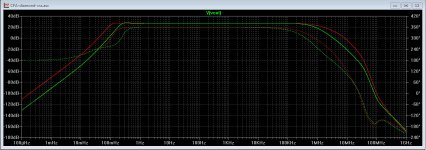
Looks strange to me. Attached, a quick'n dirty test with my Diamond VSSA, just multiplying by 10 the feedback imedance. Red is original (500) green modifiéed (5000).I have tried this amp for different reason, but was a bit surprised that it behaves the same as the one with low impedance emitter input.
It is at the limit of the margin I usually keep (5 or 10)
You can be sure that distortion will increase too, because the parasitic caps are not linear.
Attachments
Last edited:
Demian
Turns out distortion is not an issue. HF is typically crossed at 3K. Atmospheric loss can be 20 dB more by 8K. The humidity filters out most of the distortion. However as a piston has no limits on compression but very real limits on rarefaction the desired drive is asymmetric. So the output is reasonably treated as a sine wave. Any 2nd harmonic tends to be cancelled in the drive DSP.
Used to have a nice portable Tek scope to observe and tweak adjustments.
Now as a bit of humor folks who design large scale systems often size the woofer amps the largest, midrange a bit smaller and the HF the smallest. Turns out the HF needs the most, then the LF and the midrange rarely needs more than 10 watts or so. Quite different than home use.
Last edited:
Looks strange to me. Attached, a quick'n dirty test with my Diamond VSSA, just multiplying by 10 the feedback imedance. Red is original (500) green modifiéed (5000).
It is at the limit of the margin I usually keep (5 or 10)
You can be sure that distortion will increase too, because the parasitic caps are not linear.
You can't compare VSSA amp with it. I added V/A converter as high impedance input(or how Bonsai called it H- bridged but not exactly just looks as one), it is not just change of feedback network impedance, take a look again at my schematic.
If it is this: http://www.diyaudio.com/forums/solid-state/253039-unique-cfa-120-230w-amp-8.html#post4428619You can't compare VSSA amp with it. I added V/A converter as high impedance input(or how Bonsai called it H- bridged but not exactly just looks as one), it is not just change of feedback network impedance, take a look again at my schematic.
I don't even need to look at the schematic. Bandwitch is limited elsewere at 100Khz, so, no surprize you see no change at 5-10MHz ;-).
Well, you need, at least, to remove the input filter, while looking at those parasitic caps issues and compensate the amp for max (but flat) bandwidth. The spirit of CFA design is: "Fight for speed".
Last edited:
But the new analyzers don't require that filter anymore. Except, with the fairly recent Levinson amps, the relatively-low out-of-band energy extends to at least 4MHz, according to what I've heard. Back to the drawing board? Or just a kinder gentler higher-frequency filter box?
Of course this has almost nothing to do with slew rate.
Aren't those hypex in a pretty box?
If it is this: http://www.diyaudio.com/forums/solid-state/253039-unique-cfa-120-230w-amp-8.html#post4428619
I don't even need to look at the schematic. Bandwitch is limited elsewere at 100Khz, so, no surprize you see no change at 5-10MHz ;-).
Well, you need, at least, to remove the input filter, while looking at those parasitic caps issues and compensate the amp for max (but flat) bandwidth. The spirit of CFA design is: "Fight for speed".
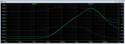
If you don't look you don't see, look second picture. Why I need to to remove input LF filter, I am showing a Loop Gain not Closed Loop Gain as you showed of your VSSA? Input LF filter has very little influence on the Loop Gain.
Yes, give-me some time to read further in your thread I just discover.I am showing a Loop Gain not Closed Loop Gain as you showed of your VSSA?
")
Anyway, this feedback impedance question is something real, that everybody have to know about. Both in CFAs and VFAs. Some try to compensate the phases turns by adding little caps in // with the feedback resistance. But it is a little tricky, and can lead to some instability.
About the dissipated power in the feedback resistances, what the hell ? You need to invest as much as you can to get the best non inductive ones, because it is there that everything happens.
About your global compensation, I agree. It is better to always take the compensation source from the output when output devices are fast enough. For two reasons.
First, as you said it includes the output stage in the comp, helping to reduce crossover distortion at HF.
Second the added charge at HF is not an issue for the output stage's very low impedance, while VAS has enough work to do without this added charge.
I sometimes had serious doubts about the validity of Plotting Loop Gain Using the Tian Method.
I prefer to make an AC Analysis at the output of the input stage or input of the VAS (right after signal of the feedback had been subtracted from the input one).
It shows a flat response curve that begins to increase when you reach the limit of the open loop bandwidth, then decrease when you reach the limits of closed loop bandwidth, in real closed loop condition.
An other advantage: you can compare in the same window the two branches of a symmetrical design and figure out any unbalance. Instant, painless and easy, no prob to add to your ASC.
Attachments
Last edited:
I sometimes had serious doubts about the validity of Plotting Loop Gain Using the Tian Method.
I prefer to make an AC Analysis at the output of the input stage or input of the VAS (right after signal of the feedback had been subtracted from the input one).
It shows a flat response curve that begins to increase when you reach the limit of the open loop bandwidth, then decrease when you reach the limits of closed loop bandwidth, in real closed loop condition.
An other advantage: you can compare in the same window the two branches of a symmetrical design and figure out any unbalance. Instant, painless and easy, no prob to add to your ASC.
Without the loop gain plot you just blind, you can see some anomalies in close loop gain, but those anomalies are better visible in the loop gain. Off course you can place the Tian probe inside where you want to see what's going on.
Does not better slew rate imply better/less IM products excited by programme noise and stage internal/device noise ?.
Dan.
Sometimes yes and sometimes no. You may for instance increase LTP current on an amp to increase slew rate, but since the vast majority of distortion is not caused by the LTP, the distortion would appear unchanged. So it matter which stage is slewing, and whether it is a significant distortion contributor.
There are much better ways to characterize distortions that occur at normal listening levels. Slew rate will give only part of the picture and may even be misleading. Some amps have low slew rate but still have all the benefits attributed to high slew rate amps.
dadod, I'm not sure to have been understud.Off course you can place the Tian probe inside where you want to see what's going on.
NO Tian in my figure. Just AC analysis. When you reach the limit of OLG, the feedback response curve begin to increase (feedback fighting to compensate the losses). So, you see all in once in real conditions and can use-it IRL as well.
And, may-be it will make some people change their minds about this "Need for speed" question ?
Last edited:
dadod, I'm not sure to have been understud.
NO Tian in my figure. Just AC analysis. When you reach the limit of OLG, the feedback response curve begin to increase (feedback fighting to compensate the losses). So, you see all in once in real conditions and can use-it IRL as well.
And, may-be it will make some people change their minds about this "Need for speed" question ?
Tian probe is used in AC analysis.
Nope.Aren't those hypex in a pretty box?
Without the loop gain plot you just blind, you can see some anomalies in close loop gain, but those anomalies are better visible in the loop gain. Off course you can place the Tian probe inside where you want to see what's going on.
I haven't made a loop gain plot in a few years, and I've had no problems. Your amp can have 150db OLG but still have 0.03% THD. Your amp can have a great phase margin but then go totally nuts when you add a capacitive load. The OLG plot doesn't leave you much the wiser as to why this actually happens.
The goal is not a loop gain plot, the goal is a stable amplifier, and the loop gain plot is only a basic tool. I think the deification of loop gain plots has kept people from thinking deeper about exactly what is happening inside the amp.
When I was still using loop gain plots, they didn't really tell me anything I didn't already know - that the amplifier was unstable. Then I still had to think meticulously and thoroughly about the phase shifts and impedances of each stage of the amp to figure out why that was. The plot didn't save me any work - I only needed it because it was how I was told to determine the stability of an amplifier. Now I save work by using more tools and techniques and not hesitating so much to apply my full range of knowledge.
When you want to improve the stability of a design, you need to be able to identify where the excess phase shift is coming from. The best tool for this is a working knowledge of the impedances and phase shifts of the individual stages, how they add up to produce a stable or unstable amplifier, and an understanding of how to probe them in the simulator.
Levinson OCA
I was surprised that there was no response from Harman in the back pages of Stereophile after the much-less-than-glowing review. All I did see was an LTE that said the things the reviewer criticized were in essence the opposite of what the reader found with his sample. I'd like to know what the private opinions of folks in the Luxury Audio group are.
I have not heard the product, let alone spent any time with it, although I recall that Toole auditioned it briefly and in a casual way (Olive et al. have yet to do amplifier DBTs afaik, although he has spoken with, characteristically, little enthusiasm, of needing to get to them someday). Floyd's comment was only They work. Despite all the figurative ink spilled in here, FT has believed that the vast majority of amplifiers have been more than adequate for many years now.
Brad Wood
Someone in here, I regret I don't recall whom, who knew the intimate details of the design, said the Levinson switcher was executed quite poorly, and that Stanley's back-to-back buck converter topology and modulation schemes were no longer required in these modern times. That approach addressed half-bridge dead time versus shoot-through issues and had some other putative advantagesAh Sorry the ML53 is in house class D. It's everyone else that seems to have gone hypex. One of the few $$$ products not to get an amazing rating in the last few years from the rags. Normally I would suggest that means it's less coloured than the boutique offerings
I was surprised that there was no response from Harman in the back pages of Stereophile after the much-less-than-glowing review. All I did see was an LTE that said the things the reviewer criticized were in essence the opposite of what the reader found with his sample. I'd like to know what the private opinions of folks in the Luxury Audio group are.
I have not heard the product, let alone spent any time with it, although I recall that Toole auditioned it briefly and in a casual way (Olive et al. have yet to do amplifier DBTs afaik, although he has spoken with, characteristically, little enthusiasm, of needing to get to them someday). Floyd's comment was only They work. Despite all the figurative ink spilled in here, FT has believed that the vast majority of amplifiers have been more than adequate for many years now.
Brad Wood
bcarso;4484554 Despite all the figurative ink spilled in here said:Good time to link this (36 year old) article Perfection: Here at Last? | Stereophile.com . Whatever one might think about the late JGH IMHO he was right.
I think most people agree that the speakers are a bigger issue than the amplifiers, but if you know how to design amplifiers what are you going to do?
Soon enough I will get brave enough to start modding my speakers.
Good time to link this (36 year old) article Perfection: Here at Last? | Stereophile.com . Whatever one might think about the late JGH IMHO he was right.
I think most people agree that the speakers are a bigger issue than the amplifiers, but if you know how to design amplifiers what are you going to do?
Soon enough I will get brave enough to start modding my speakers.
One can now do arbitrarily-fine-mesh on-axis frequency response compensation, even tailor it to compensate for sample-to-sample variations of the drivers. One can in principle linearize the transducers, closing the loop as it were with the power amps, to drastically reduce nonlinear distortion, although afaik this has been achieved by-and-large only with low frequency ones. But none of this accounts adequately for what most of us prize for audio reproduction in smallish rooms (versus say concert halls, or stadiums), and doesn't help poor program material.
I don't buy the notion that, because loudspeakers distort a lot, this means we don't have to worry about amplifiers. Although I know of no tests that would pass muster as properly "scientific", I think we can, to some extent, "hear through" a system and identify things that are on the face of it overshadowed by loudspeaker distortions. But usually what is wrong, and what detracts from the enjoyment of music, are issues with the nature of the spatiotemporal soundfield. Progress has been made, and as well our ability to adapt to less-than-optimal conditions and still hear the music is really astonishing.
- Status
- Not open for further replies.
- Home
- Member Areas
- The Lounge
- John Curl's Blowtorch preamplifier part II