No, thtats one item that I need to get.Do you have a clamp-on current meter?
-RNM
Dan.
For measuring these low currents clamp ons are not too helpful. You could make a current trasformer with a Ferrite toroid or use a 10 or 100 Ohm resistor and a differential voltage probe. Most interesting usually is the spectrum. it tends to be a mix of switcher supply crud, line harmonics from transformer leakage and local radio stations.
The HF components can easily find their way into sensitive parts of a DAC or whatever and muck it up. Since they may well be data related they will show during audio playback and not during test signals.
Finding clean ways to route this stuff away from the sensitive parts of the circuitry is important, and what Marce spends his days working through. Single point grounds won't help here.
I was just playing with the Adjust+ record player measurement system and to my dismay the RPM of my player was shown as way too low, out of tolerance. Yet it sounded fine with music. Hmmm. Then I discovered that Adjust+ was assuming the soundcard sampled at 44.1k whereas the soundcard though it had to do 48k...
Jan
I am happy you found out before disassembling the record player!
The jitter analyzer arrived..... nice with two inputs to do comparisons. Internal or external master clock.
Audibility of jitter? How much is too much? ... and what can be done about it or to improve on it from the user view point;
A few of many re. jitter:
View attachment 483784
View attachment 483786
View attachment 483783
View attachment 483785
Too bad this site doesnt allow larger file size... some very good stuff cannot be included here.
Most of the efforts go into the practical design and its limitations and how to improve on them and not about the theory.... which i hear too much about here at DIY-land. IMO.
THx-RNMarsh
Please note that while SY opined 5-10 nS and Demian 20-100 pS the unstated was frequency and where you are measuring.
200nS of jitter in a 48k AES or SPIDF data stream is way too much. So please be sure to mention how you are doing your measurements.
The other issue is how you are doing your listening. Mono in headphones may be most sensitive but stereo might show different artifacts. If you are using loudspeakers the a note about background noise and listening level would be nice.
Now I have a bone to pick with you. Ever since I mentioned to you on the Shibasoku thread about the Panasonic analyzers you picked up a few and encouraged others to do so. Now their price has doubled!
I think I need to give you some stock tips!
")
ES
The jitter analyzer arrived..... nice with two inputs to do comparisons. Internal or external master clock.
Audibility of jitter? How much is too much? ... and what can be done about it or to improve on it from the user view point;
A few of many re. jitter:
View attachment 483784
View attachment 483786
View attachment 483783
View attachment 483785
Too bad this site doesnt allow larger file size... some very good stuff cannot be included here.
Most of the efforts go into the practical design and its limitations and how to improve on them and not about the theory.... which i hear too much about here at DIY-land. IMO.
THx-RNMarsh
Dick how does this new analyzer compare to this functionality in the AP?
BTW One of those links says it succinctly: 'This interface jitter has absolutely no effect on the audio unless it influences the clocking in the DAC'. Hear hear!
Jan
Last edited:
The jitter analyzer arrived..... nice with two inputs to do comparisons. Internal or external master clock.
Audibility of jitter? How much is too much? ... and what can be done about it or to improve on it from the user view point;
A few of many re. jitter:
View attachment 483784
View attachment 483786
View attachment 483783
View attachment 483785
Too bad this site doesnt allow larger file size... some very good stuff cannot be included here.
Most of the efforts go into the practical design and its limitations and how to improve on them and not about the theory.... which i hear too much about here at DIY-land. IMO.
THx-RNMarsh
Dick how does this new analyzer compare to this functionality in the AP?
BTW One of those links says it succinctly: 'This interface jitter has absolutely no effect on the audio unless it influences the clocking in the DAC'. Hear hear!
Jan
And that may require buffering to change from a PLL recovered clock to a more stable one.
And that may require buffering to change from a PLL recovered clock to a more stable one.
Ohh yes, not saying jitter isn't an issue. But it should be clear where to apply the efforts and that it is less useful to worry about it upstream.
Jan
The more I read about jitter for audio reproduction the more I think its a sort audio bogyman to frighten us from digital....
Most of the less esoteric data I have read puts figures around 10-30ns range for audible jitter and a lot of information I have seen put up here and from Google searches states that this is easily achievable in most systems... And the only place jitter is critical is at the final stage Digital to Analogue conversion (or visa versa), it cant be recorded, as long as the bit pattern is unchanged during signal transmission from source to destination it is irrelevant yet there seems to be a whole mystique building up around it, with jitter figures that in some cases would be hard to achieve on communication systems.
So I wonder is this just another Audiophile neurotic witch hunt that has gone beyond what are sensible and achievable jitter figures...
Especially for Ed:
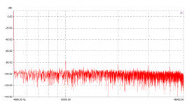
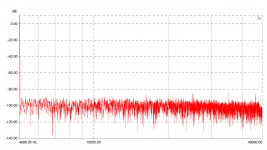
Two measurements of my QUAD 405-2 at 1W into 8R. Bridge tuned for minimum 3rd. One is with stock 330k (!) feedback resistor around the input opamp. The other is with this resistor replaced with 5 x 68k quality film R!
The small black cross in the noise is the 3rd.
Sometimes you are right on target Ed
Jan
Attachments
The more I read about jitter for audio reproduction the more I think its a sort audio bogyman to frighten us from digital....
Or in order to sell you a "cure."
se
Thank you Ed, Demian.
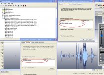
I did some reading since yesterday. The 24/96k is indeed considered the limit for native mode USB Audio Class 1 drivers Audio USB.
I also read that the overhead alone can amount up to 10%-15% of the channel data traffic.
In this PC there are five USB controllers. The four are tagged (each) as reserving 10% of BW for the system. The one that handles the external sound card, reserves 12% for the system and assigns 71% of the BW to the card.
Question 1: Is each USB controller managing 12Mbps or all five are sharing the 12Mbps?
Question 2: What is the 100% BW? The 12Mbps, the 480Mbps, something else?
Single point ground when implemented properly (most frequently witnessed by the absence of hum, buzz), is only good for minimizing ground loops.
When dealing with HF signals or noise, "Follow the Path of Least Impedance" (hi JN)
http://www.analog.com/media/en/training-seminars/tutorials/MT-031.pdf
Successful PCB Grounding with Mixed-Signal Chips - Follow the Path of Least Impedance - Tutorial - Maxim
For those that are that much interested investigating the issue of jitter:
https://www.jitterlabs.com/support/calculators/
George
I did some reading since yesterday. The 24/96k is indeed considered the limit for native mode USB Audio Class 1 drivers Audio USB.
I also read that the overhead alone can amount up to 10%-15% of the channel data traffic.
The bandwidth is shared and between other reserved use and the way the system communicates 24/96 is the highest you can get on a 12 Mbps link. Also if you have even a mouse sharing the link you will have problems. Most PC's have only 1 or maybe 2 USB controllers so all the traffic passes through the same controller.
In this PC there are five USB controllers. The four are tagged (each) as reserving 10% of BW for the system. The one that handles the external sound card, reserves 12% for the system and assigns 71% of the BW to the card.
Question 1: Is each USB controller managing 12Mbps or all five are sharing the 12Mbps?
Question 2: What is the 100% BW? The 12Mbps, the 480Mbps, something else?
Finding clean ways to route this stuff away from the sensitive parts of the circuitry is important, and what Marce spends his days working through. Single point grounds won't help here.
Single point ground when implemented properly (most frequently witnessed by the absence of hum, buzz), is only good for minimizing ground loops.
When dealing with HF signals or noise, "Follow the Path of Least Impedance" (hi JN)
http://www.analog.com/media/en/training-seminars/tutorials/MT-031.pdf
Successful PCB Grounding with Mixed-Signal Chips - Follow the Path of Least Impedance - Tutorial - Maxim
So I wonder is this just another Audiophile neurotic witch hunt that has gone beyond what are sensible and achievable jitter figures..
.
For those that are that much interested investigating the issue of jitter:
https://www.jitterlabs.com/support/calculators/
George
Attachments
Last edited:
Apart from the very rare board, most boards I have been involved in have all had ground planes, some where power is involved or other requirements for isolation have had separate ground planes joined at a robust point,some Analogue digital designs will split the analogue from the digital ground, but again the join tends to be quite large, this falls down somewhat when there is more than one convertor on a board. Best results come from a contiguous ground plane (though there may be several actual physical planes in a design).
What I don't do and only see on DIY audio sites are the horrible spiders legs type grounds with many spurs coming from one point!!!!!!! Horrible especially for EMC purposes.
One interesting fact, many years ago we would do digital boards with the interlaced power routing (similar to E I transformers) but would never do analogue boards without ground plane(s).
Interesting one on PC USB, found this that may help...
motherboard - When I connect 4 USB drives to my PC at the same time, does each slot have 480 Mbit/s? - Super User
So I would presume that handling 12Mbps should be achievable for the external sound card as it has a share of the total USB controllers bandwidth of 480Mbps, if only one controller.
Please note that while SY opined 5-10 nS and Demian 20-100 pS the unstated was frequency and where you are measuring.
200nS of jitter in a 48k AES or SPIDF data stream is way too much. So please be sure to mention how you are doing your measurements.
The other issue is how you are doing your listening. Mono in headphones may be most sensitive but stereo might show different artifacts. If you are using loudspeakers the a note about background noise and listening level would be nice.
Now I have a bone to pick with you. Ever since I mentioned to you on the Shibasoku thread about the Panasonic analyzers you picked up a few and encouraged others to do so. Now their price has doubled!
I think I need to give you some stock tips!
ES
The 20ps -200ps are the correct numbers for audibility... High freq to low, respect.
Somehow, the people who have analyzers to sell must be watching DIY forums..... even the lowly HP 339A has doubled! But, hark! The good news is that no one bid on one that was too high recently... so they may come back down soon. Good luck.
-Richard
Last edited:
Dick how does this new analyzer compare to this functionality in the AP?
BTW One of those links says it succinctly: 'This interface jitter has absolutely no effect on the audio unless it influences the clocking in the DAC'. Hear hear!
Jan
I dont know how it compares to A-P. The A-P has its strengths, of course. But, the A-P is so clunky in its software that i tend not to use it for anything much that I cant get quicker and easier with other instruments. Now, it may be a piece of cake, i dont know. Dedicated instruments do the job without as steep learning curve just to set it up for proper operation and not mess up on some details or quirk.
The dedicated instrument has the processing in SW and HW optimized and displays it in many forms with the touch of a button. Or, in this case, a touch screen. .... you can get an idea of its usefulness to you by downloading the operations manual for the Yokogawa TA320. The time it saves me over the A-P is worth the price IMO.
-Richard
Last edited:
Interesting one on PC USB, found this that may help...
motherboard - When I connect 4 USB drives to my PC at the same time, does each slot have 480 Mbit/s? - Super User
So I would presume that handling 12Mbps should be achievable for the external sound card as it has a share of the total USB controllers bandwidth of 480Mbps, if only one controller.
Thank you Marce, it helps.
They make it clear that each USB Host Controller is assigned the full bandwidth (12Mbps for USB 1.x, 480Mbps for USB 2) and splits it among the devices that are attached to it.
What I don't do and only see on DIY audio sites are the horrible spiders legs type grounds with many spurs coming from one point!!!!!!! Horrible especially for EMC purposes.
Horrible compared to a groundplane I guess. And I agree.
But what about if we compare this spider leg ground type to a daisy-chained return traces type of (single sided) pcb?
George
No, thats one item that I need to get.
Dan.
The TEK P6042 can be found on eBay etc and covers a wide current and freq range.
THx-RNMarsh
What I don't do and only see on DIY audio sites are the horrible spiders legs type grounds with many spurs coming from one point!!!!!!! Horrible especially for EMC purposes.
If done right it works perfectly fine, but it is for prototyping on matrix board. Sure, there are problems. You mentioned EMC pick up, so you have to shield all this little antennae really well. Another potential problem is inductance, so you have to keep it compact, but then again, when it is only for audio freqs, this is only marginally important methinks.
Getting back to FETS (and tubes), it is interesting how different companies and fabrication methods change the essential nature of the part. All we often see is a symbol, along with some textbook theory like: Fets generate 2'nd harmonic almost exclusively, and tubes are even more linear and follow Child's law essentially. However, each device type and manufacturer can be significantly different in PERFORMANCE.
The Hitachi 2SK214/J77, mosfets, for example are lousy in this design, AS SHOWN. A semiconductor curve tracer will show this as well.
Tubes also have measurable differences, even with the same tube part number. Of course, those with tin ears and lovers of feedback can dismiss these differences.
The Hitachi 2SK214/J77, mosfets, for example are lousy in this design, AS SHOWN. A semiconductor curve tracer will show this as well.
Tubes also have measurable differences, even with the same tube part number. Of course, those with tin ears and lovers of feedback can dismiss these differences.
John,
You emphasise ' AS SHOWN" - what would improve the Hitachi MosFet performance in a line amp type application ?
Borbely cascoded the 2SJ77/2SK214 (79/216) as the output devices in his mid period line and phono stages, but later removed the cascoding as he felt (and apparently so did Nelson) that cascoding worked for voltage gain stages, but not current gain. The output pair cascoding measured well, but lacked dynamics when auditioned.
Erno increased the uncascoded 77/214 output pair bias from 50ma up to 70 to 100ma in later line and phono applications
Last edited:
- Status
- Not open for further replies.
- Home
- Member Areas
- The Lounge
- John Curl's Blowtorch preamplifier part II