Scott
I actually prefer to use perlite in the floor of rooms I design for sound issues. Now on my last trip to Buffalo on the Canadian radio station I was listening to, they had an ad for folks who removed it from homes! Unaware of any issues with it.
The reason why it is useful is that it is very light weight and if there are vibrations in the floor it will bounce around and change the energy to a higher frequency where it is more easily absorbed.
So your quote of the folks who were building their own quiet space indicates to me they only tried increasing the mass for more attenuation. My house has 10" of masonry and then 4" of studded wall with fiberglass fill. The noise comes in through the windows which are double glazed and then there is a third isolated light weight sound barrier. The noisiest item is the hot water heater exhaust fan in the basement. In the bathroom that has a hot water radiator the water pump circulating the water does make enough noise it can be heard.
Even though it is in a suburb, with modest local street traffic the ambient noise at night can drop below 25 dba. It turns out that if you get a bit more into the country the noise level goes up from crickets and such. However it is rural enough that a deer ate all of my tulip flowers.
Of course there is an active railroad track a few hundred feet away and I can hear the trains horn at night.
Jan:
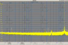
It looks like your testing the jitter tolerance of the SPDIF receiver. The current generation is really very good. The Jtest is a better tool for testing since it creates the most stress on the receivers jitter rejection. You do need to use Fs/4 or Fs/2 to see the jitter since lower frequencies are less sensitive to it. And a high resolution FFT since you are looking for close in sidebands.
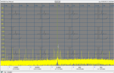
Here are some examples. (JK generator to AK4490 demo board at 44.1 KHz 24 bit) All the jitter sidebands are close to the 12 KHz tone. The second image is formatted similar to the Stereophile format. (AK4399 demo board and the JK generator).
It looks like your testing the jitter tolerance of the SPDIF receiver. The current generation is really very good. The Jtest is a better tool for testing since it creates the most stress on the receivers jitter rejection. You do need to use Fs/4 or Fs/2 to see the jitter since lower frequencies are less sensitive to it. And a high resolution FFT since you are looking for close in sidebands.
Here are some examples. (JK generator to AK4490 demo board at 44.1 KHz 24 bit) All the jitter sidebands are close to the 12 KHz tone. The second image is formatted similar to the Stereophile format. (AK4399 demo board and the JK generator).
Attachments
Yes, EUVL, R1,2,3,4 are for biasing the jfets.
There is some difference of opinion as to whether hi Gm jfets need biasing, and Erno Borbely as well as Nelson Pass have produced circuits without biasing. I prefer to use some bias, although on peaks the jfet might get forward biased to some degree.
Resistor biasing allows easier setting of the idle current and is still very necessary with low Gm jfets. However, what actually happens at the input gate during the transition between negative bias and positive bias is an unknown to me, so I prefer to have some negative bias.
Of course, using 4 resistors when one could possibly do, omits the fact that the GAIN SET RESISTOR (going sideways) can be changed at will, without effecting the bias. This can be very useful.
My answer will probably generate some controversy.
I noticed that complex assemblies (I mean things like Cascode, Super pairs, diamonds etc....) always help to reduce distortions or other evils. BUT they often add a "signature". I'm referring to Cascode, as the most obvious for me.
It is totally subjective, and hard to generalize. Well, totally subjective, not really, you can measure the changes. Added poles, increase of bandwidths etc.
To precise my question, i believe there is in everything (Distortion, noise, slew-rate), a blurred threshold where an improvement do not bring any benefit.
On the contrary, it seems to me than too complex amplifiers, with a lot of active devices lose details in music reproduction, compared to very simple ones.
Complicated question, implying to can figure out our thresholds (Like Richard said ;-), a little philosophical, with fashion or snake oil traces for pure objectivists, but i should be really happy to read as much 'opinions' as possible on this subject.
How far did-we have to go when we take decisions about topologies starting a power amp design ?
Define "complex".
If you refer to say the number of semiconductors used, then this brings into play also how and for what purpse they were used.
An example to illlustrate, HK PA2400. Power amp rated at 170W/8. Each channel uses a fully complemetary topology, with 2SK170/2SJ74, cascoded with 2SC2240/2SA970 - that's 8 transistors, The complementary VAS stages use 3 transistors each, 6 altogehther, total 14 devices. The simlated zener for bias uses 2 more, that's 16. Predriver and driver (in a Darlington connection) add 4 more, that's 20. Four power stage pairs, that's 28. But, the input stage CCS is very complex, and uses a total of 7 BJTs, unusually many, total 35. 1 more for overload sensor, that's 36 devices per channel.
That's a lot of devices, relatively speaking, so the natural question is - what's the payback? Into an IHF load, it delivers nominally 170W/8 Ohms, which measures as 191W/8, 370W/4 and 610W/2 Ohms. It's as clean as a whistle, and as far as I could tell, using my own, AR94 and JBL Ti600 speakers, it has zero change in tonality no matter what I do, including making my window panes rattle, much to the joy of my neighbors. It does bass lines like no other amp I have ever heard except the Krell, but - and this is not characteristic of H/K - it does mid and treble range oustandingly well. And it does all that with just 12 dB of GNFB, with a closed loop bnadwidth of -3 dB at <1 Hz ... 360.000 Hz and a slew rate of > 150 V/uS.
I cannot vouch for wjether the complex input stage is responsible for all or much of that, but intimately I believe they knew damn well what they were doing. Its grip on the speakers is truly outstanding, it seems as if you could connect a shoe box, call it a speaker and it would drive it. And, very important to me, it has that air of efortlessness, as if it were an endless supply of power, obviously an illusion, but the best one of them all. Admittedly, the Marantz 170DC also does that, but it is not quite as transparent overall.
Now, Christophe, if you can do all that with less devices, I'll agree that it is too complex, but not until then. The question is not whether something is too complex or not, but does it deliver the goods across the table or not. That is THE challenge.
Projects with less devices are naturally favored by DIYers because they don't have half the measurement gear people here have, even discounting the true geeks, like John, Richard, Pavel, Damian, Brad, etc. but let's not forget that this is their job and their profession, so to them, that's no overdoing it, it's supplying tools for work.
To me, "complex" means that someone used a lot of materials but with results which make me wonder where did all that go to. If it comes on song, I'll never need to ask myself that.
Last edited:
...
... However it is rural enough that a deer ate all of my tulip flowers.
Of course there is an active railroad track a few hundred feet away and I can hear the trains horn at night.
Russ(el Dawkins) also had the same problem, if memory serves. Ask Russ how he coped, but knowing him, I venture the guess that he just smiled and wished that deer bon apetit.

Not to the point
To me, to the point. I can hear the difference, I can make it in ABX, and I am asking and seeking for the best possible solution. So, hires makes a lot of sense, to me. I do not care about mediocre recordings (where mp3 is enough), I do not listen them.
For charge preamps, running with some reverse bias on the input gate is important, to minimize any loss of charge to forward conduction. But it seems that for the high gm parts they work just fine with up to a couple hundred millivolts. Gm just gets higher and the excess current noise is usually negligible. Of course this falls apart for several hundred millivolts.Yes, EUVL, R1,2,3,4 are for biasing the jfets.
There is some difference of opinion as to whether hi Gm jfets need biasing, and Erno Borbely as well as Nelson Pass have produced circuits without biasing. I prefer to use some bias, although on peaks the jfet might get forward biased to some degree.
Resistor biasing allows easier setting of the idle current and is still very necessary with low Gm jfets. However, what actually happens at the input gate during the transition between negative bias and positive bias is an unknown to me, so I prefer to have some negative bias.
Of course, using 4 resistors when one could possibly do, omits the fact that the GAIN SET RESISTOR (going sideways) can be changed at will, without effecting the bias. This can be very useful.
Van der Ziel in one of his many books Noise in Measurements advocates floating gate mode for some sources, and some condenser mic capsule preamps do this as well. On the one hand the shot noise in the gate current, being a balance of forward conduction and drain-gate leakage, is 3dB worse than 0 bias with Idg alone; but the upside is the elimination of a high-value feedback or input resistor, or some more complicated means of resetting the charge, if there is a net charge signal from the source.
Jan:
It looks like your testing the jitter tolerance of the SPDIF receiver. The current generation is really very good. The Jtest is a better tool for testing since it creates the most stress on the receivers jitter rejection. You do need to use Fs/4 or Fs/2 to see the jitter since lower frequencies are less sensitive to it. And a high resolution FFT since you are looking for close in sidebands.
Here are some examples. (JK generator to AK4490 demo board at 44.1 KHz 24 bit) All the jitter sidebands are close to the 12 KHz tone. The second image is formatted similar to the Stereophile format. (AK4399 demo board and the JK generator).
Thanks Demian, I'll give it a shot. Note that I only did this because Ed and Dick kept on asking for measurements, but apparently they are not really interested, just trolling, so I'm not sure how much more time I want to invest in this.
Jan
Thanks Demian, I'll give it a shot. Note that I only did this because Ed and Dick kept on asking for measurements, but apparently they are not really interested, just trolling, so I'm not sure how much more time I want to invest in this.
Jan
Trolling? No, I asked if you ever found jitter degeneration in CD duplicates. I have a bit of background in audio digital signal transport. I suspect I will have to break down and buy some CD blanks.
Trolling? No, I asked if you ever found jitter degeneration in CD duplicates. I have a bit of background in audio digital signal transport. I suspect I will have to break down and buy some CD blanks.
You specifically asked me to do the measurement.
You specifically asked me to do the measurement.
? My memory must be failing. I though I asked specifically about duping CDs.
Regarding negative resistance: an offshore subcontractor to Harman got concerned when we had a rash of slow-starting (like 30s) crystal oscillators (due to board contamination/leakage in the vicinity of a TSSOP uC package throwing the bias of the gate oscillator off and into a region of lower gain). They read the crystal manufacturer's specification, and asked us where they could source a specific negative resistor.
It was challenging to formulate a reply.
Haha, that's very funny. It needs to be saved in the hall of fame of analog design humor.
Even better, maybe you can post the whole email with the names removed.
? My memory must be failing. I though I asked specifically about duping CDs.
67853
I remember an experiment years ago. Comparing duplicate CD's with the original. The first duplicate was better, mainly because it did not have stamped pits and had error correction. A duplicate of the that first duplicate was better. By the third cascaded duplicate the signal was not as good. This was an internal experimented. Do not know if it was ever published.
? My memory must be failing. I though I asked specifically about duping CDs.
Duplicating is also what i am interested in as that is what we do at home (from files and other CD's) and not pressing/stamping CD's.
Once the glass plate is made for stamping our CD's... all the jitter, multiple dithering, compression, EQ, Effects and what ever is locked in. A perfect copy of THAT isnt very useful to getting better sound repro. But what can you do.... well you can go to HD Mastered files and downloads which minimizes a lot of the problems. I dont have to depend on any CD players issues on this end. Just the HD files and a good DAC.
Why all the bother with CD when there is now an alternative that in NO Way is worse.
THx-RNMarsh
For a while I printed out emails and saved them, but I fear that exchange got buried. Yes, it was a hoot and a half.Haha, that's very funny. It needs to be saved in the hall of fame of analog design humor.
Even better, maybe you can post the whole email with the names removed.
It was also an example of a reflow process that left contamination, or possibly a bare board problem. Some guarding would have helped. I think we got them to better tune their process, and there was a slight reduction in the value of the d.c. feedback bias resistor.
- Status
- Not open for further replies.
- Home
- Member Areas
- The Lounge
- John Curl's Blowtorch preamplifier part II