BTW, for the interested, if you want to experiment with the concept yourselves, the European magazine "Elektor" published a version of it which was much simplified, cheap to make with off-the-shelf parts crying out to be upgraded, using a SEPP output stage with Ti's TIP 142/147 Darlingtons. I actually made one for fun a long time ago, and it did play better than one would expect such a simple project to do.
If there's interest, I can look into my librarry, I think I still have it somewhere (a scan of the page).
If there's interest, I can look into my librarry, I think I still have it somewhere (a scan of the page).
Note that the notion of a (more) linear amp working in conjunction with a cruder one keeps being reinvented and declared as the ultimate. Devialet is one company that comes to mind.
When we look back on the days when power transistors were mostly quite slow, the rationale has more appeal. Alternatives included local loops following Hawksford's approach (see Cordell's embellishments and discussions in his book). Rich May told me that Sumo's power amps were able to use 2N3773 devices with local correction despite their very limited bandwidth, and that moreover the migration to DMOS was a marketing decision.
When we look back on the days when power transistors were mostly quite slow, the rationale has more appeal. Alternatives included local loops following Hawksford's approach (see Cordell's embellishments and discussions in his book). Rich May told me that Sumo's power amps were able to use 2N3773 devices with local correction despite their very limited bandwidth, and that moreover the migration to DMOS was a marketing decision.
I think Walker's approach suffered from the name "current dumping".
Probably, that and almost no marketing at all. It got much more attention in design circles than in the marketplace.
Also, Peter's goal was not to produce a better amp, but an amp as good as the next but not needing (expensive and unreliable) bias adjustment. That goal was completely successful.
Jan
The Quad 405 was a subjectively lousy sounding amp. It DID measure fairly well, BUT it failed with one particular test: NOISE LOADING The 'current dumping' concept works well, but Quad, in their wisdom, put all their faith in the distortion balancing, and not into the circuit or the parts to make it. It also had very early current limiting, so it could not drive many loads properly.
When the current dumping idea was put into WW, I tried it for a preamp as well, just using resistors. It gave about 20dB less distortion, than feedback alone. A very good way to fix a class C output stage, like what was used as the line amp for the STUDER A-80 Mk2. I even went to Zurich and showed my 'upgrade' to the line amp to Willi Studer himself. I had the evidence, but the engineers never used it. Oh well.
It is interesting that John Atkinson lived with a Quad 405 for awhile, then realized that it had to go. That is reality for you, above harmonic distortion measurements.
More empty hand-waving. If only we could harness the energy from all that instead of it just being wasted as heat.
se
No. I have recordings to confirm. Never seen any real work of yours, over years here, but plain arguing and disputing.
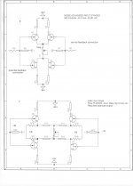
Edit: attachment from a presentation I once did gives the concept.
The constraint should be: R1 x R4 x C3 = L2
This way, the units are correct as well.
No. I have recordings to confirm. Never seen any real work of yours, over years here, but plain arguing and disputing.
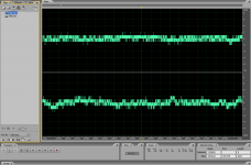
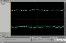
Pavel, I've tried to record noise at -93dB (about the level of 16 bit dithered silence) and when played back set for normal listening I hear nothing. What do you mean?
Pavel, I've tried to record noise at -93dB (about the level of 16 bit dithered silence) and when played back set for normal listening I hear nothing. What do you mean?
Try this:
https://www.dropbox.com/s/fzptrndp7avwya5/16b_24b.zip?dl=0
16 bits x 24bits, same recording (a friend of mine, enthusiast). Take a very good audio equipment, no notebooks, no smartphones. Warning, initial part has very low volume, followed with high volume kicks. In the first half, you may hear quantization noise from 16b file, with good headphones and good headphone amplifier. Please feel free to make any file analysis, you will see quantization noise in the 16b file and not in the 24b file. You may also make your own TPD dithered 16bit file from the 24b file to see and hear the added noise.
For those who do not have dropbox account, click outside login box window and you will be able to download the file then.
The constraint should be: R1 x R4 x C3 = L2
This way, the units are correct as well.
So how does that remain intact over frequency then? Remember, I was talking about the concept. I said C and L but in a more detailed analysis it is of course the impedance of the L and C that is the thing.
Jan
So how does that remain intact over frequency then?
Jan
The original equation was in impedances, where Z(C) = 1 / ( 2 x pi x f x C ) and Z(L) = ( 2 x pi x f x L).
That's why the constraint equation changes form when replacing the impedances Z(L) and Z(C) with the above.
Walker's original equation was: Z(L2) x Z(C3) = R1 x R4
Then substituting for the impedances, L2 / C3 = R1 x R4
We then have the time constant (L2 / R1) = the time constant (R4 x C3) as the condition of balance.
Note that the presentation equation does not have consistent units and so cannot be correct.
Last edited:
The original equation was in impedances, where Z(C) = 1 / ( 2 x pi x f x C ) and Z(L) = ( 2 x pi x f x L).
That's why the constraint equation changes form when replacing the impedances Z(L) and Z(C) with L and C.
We then have the time constant (L / R) = the time constant (R x C) as the condition of balance.
Note that the presentation equation does not have consistent units.
Walker's original equation was: Z(L2) x Z(C3) = R1 x R4
Then substituting for the impedances, L2 / C3 = R1 x R4
Indeed, fully agree. Thanks for the amplification.
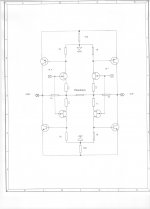
Edit: I used one of the resistors to tune the bridge which nulled the odds. Why is that, why not ALL harmonics? What do you think would happen if I tune the cap?
Jan
Last edited:
Hi Dan,
No, we wish we could have a Vendetta!
")
You missed my cryptic sly dig....... they have some kind of Vendetta.
Dan.
Last edited:
Sad, but true.No. I have recordings to confirm. Never seen any real work of yours, over years here, but plain arguing and disputing.
Dan.
Sad, but true.
Dan.
Plain arguing is a valid contribution. At least as valuable as presenting undemonstrated conclusions in the hope of having them accepted as true on the basis of repetition or simply trying to slip them past proper scrutiny by disguising them in yet another restatement.
Stating that digital artifacts are less audible in 24-bit than 16-bit is just another way of trying force the fact that you can't hear the difference through the eye of the needle. It's truly insulting that anybody should believe that the rest of us can't see through this kind of semantic jiggery-pokery.
Indeed, fully agree. Thanks for the amplification.
Edit: I used one of the resistors to tune the bridge which nulled the odds. Why is that, why not ALL harmonics?
What do you think would happen if I tune the cap? Jan
In theory, tuning any one of the four parts should yield the same results as the others. In practice, things may be a little different.
The capacitor is rather small in value also, only 120 pF. Maybe the evens are in the class A amplifier.
Last edited:
Try this:
https://www.dropbox.com/s/fzptrndp7avwya5/16b_24b.zip?dl=0
16 bits x 24bits, same recording (a friend of mine, enthusiast). Take a very good audio equipment, no notebooks, no smartphones. Warning, initial part has very low volume, followed with high volume kicks. In the first half, you may hear quantization noise from 16b file, with good headphones and good headphone amplifier. Please feel free to make any file analysis, you will see quantization noise in the 16b file and not in the 24b file. You may also make your own TPD dithered 16bit file from the 24b file to see and hear the added noise.
For those who do not have dropbox account, click outside login box window and you will be able to download the file then.
Whatever, I don't hear a thing.
Just a gentle fight between two opposite schools: Simple, and highly optimized to reduce noises and distortions or Distortions reduced by design (complex).
I have no idea of the best way. Somewhere in the middle, as usual ?
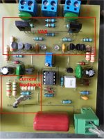
I just saw "simple". Member still4given just fired up the "eyesee".
Just the "mocked" TL072/NE5532 IC can do what a much more involved
discrete design can do (at 100W).
The limited performance of these old IC's is circumvented by V/I use -
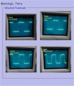
it seems (>50V/us slew - nice 100k square waves).
Scope (below) says it can match anything discrete (VFA). Listening impressions
were in line with leach/blameless/"advanced".
"Somewhere in the middle" can be both simple / high performance (and
a CFA
) .OS
Attachments
Last edited:
- Status
- Not open for further replies.
- Home
- Member Areas
- The Lounge
- John Curl's Blowtorch preamplifier part II