My reference is the direct bypass although i can not mimic the highpass action of the caps that way. Yes, i should include an electrolytic but they are not availlable in 10nF.
I did this kind of comparison with caps for my speakers but not in the ampilication chain that way. Yes, it was fun but also very tyring and ultimatively quite frustrating too. Especially Martina Schöner is extremely hard to satisfy. After hours listening to Ann Sophie von Otter singing Weil she said : "Could you please combine the natural chest resonance of this cap with the nice resolution of silbilants of that cap".
The test for speaker caps did not use a switch. I used 2mm Multicontact connectors.
I've moved your book to the top of my Christmas Wish List after Rene Yeager (who had just finished your book), gave it a very high recommendation last Saturday at an informal gathering.
High Praise indeed!
Best Regards,
TerryO
Hi Terry,
Thanks for your very kind words, and please convey my thanks to Rene. I hope Santa is good to you and that you enjoy the read.
Cheers,
Bob

I could do it, and I may, sometime. I am pretty sure that you will find that I am correct on this matter. It is the only explanation that really makes any sense. While the 741 is an old design for a number of reasons, it is the PROTOTYPE for 100's of audio designs still used in virtually every commercial audio design today, and it has only been improved slightly. Why? Because it is included as building block in virtually every complex consumer IC, such as TV and CD circuitry, for the last 40 years.
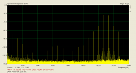
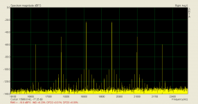
That shows nothing, unless you look at each and EVERY component and note its mathematical derivation. This is the BIG mistake! FM sidebands CAN be superimposed on IM and get lost in the complexity. However LOOK for SYMMETRY around the test signal dominant components. Looks like FM to me!
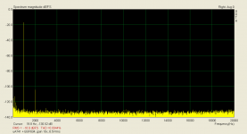
Even for much lower amplitude we get horrible result. The CCIF IMD 19+20kHz (the 3rd order component) is a very revealing test method regarding even soft slew rate limitation. More revealing than multitone testing, and more revealing than the DIM test (sine + square).
Attachments
That shows nothing, unless you look at each and EVERY component and note its mathematical derivation. This is the BIG mistake! FM sidebands CAN be superimposed on IM and get lost in the complexity. However LOOK for SYMMETRY around the test signal dominant components. Looks like FM to me!
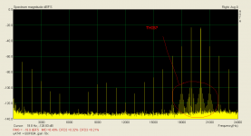
This (red circle)? This is modulated by PSU frequency, when SR limited. One measurement is faster and easier than 100 web pages.
Attachments
If anyone here is seriously interested in this, I recommend finding Matti Otala's other papers regarding TIM distortion also published in the 1970's and go through them carefully to note that he already compared virtually every kind of distortion measurement then used, including SMPTE IM, CCIF IM, Harmonic, with TIM and found both good and bad aspects of each. He made DETAILED comparisons, not hand-waving. I rest my case.
Besides i am working on the little cap switchbox and this is how far i got.
I would not consider using this type of switch and jacks in a really nice system. Should a cap switcher box be less demanding?
If anyone here is seriously interested in this, I recommend finding Matti Otala's other papers regarding TIM distortion also published in the 1970's and go through them carefully to note that he already compared virtually every kind of distortion measurement then used, including SMPTE IM, CCIF IM, Harmonic, with TIM and found both good and bad aspects of each. He made DETAILED comparisons, not hand-waving. I rest my case.
I know his papers. Anyway, I prefer Cabot's "COMPARISON OF NONLINEAR DISTORTION MEASUREMENT METHODS".
And, we have much more sensitive measurements now to make a proof, compared to the seventies. Again, measurements do reveal much more than the discussion.
You are the one who serves no proof, but old stories.
Last edited:
I was there when Cabot gave his paper. He made a few 'cheap shots' at Otala, similar to some recently here, and I reminded him that he did NOT use the same op amp model as Otala, and therefore he should not expect the same distortion results. In other words, if he expected the same results, he should use the same models.
I would like to talk about NEW measuring methods vs OLD design measuring methods, as well as NEW compared to OLD research.
Of course, newer test equipment, in principle, can give you lower residual distortion, and perhaps, even better resolution. However, is it really that much different? No, not really. In fact, I can get more info from a B & K graphic recorder, than I can with a modern computer, printout for printout. Does everyone realize this?
What has really changed is the time taken to make a measurement, and the cost of making pretty good measurements. Yet, when I was at Ampex 42 years ago, we could make measurements and graphs as informative as almost anyone here, with their fancy new equipment.
Now, what about specifics? Well, the HP3581, used for the Otala TIM measurements, has a digital readout to 1 Hz. How many of you, including you, PMA, have scanned EACH frequency with output and correlated its origin? You did little with the last plots that you presented. You just posted a 'display', implying that is all that there is to it.
To understand what is REALLY going on, sometimes further scrutiny is needed of EACH and EVERY component. Then, maybe, just maybe, FM distortion 'might' creep in between the expected distortion products. THAT is the question that I am raising.
Now, why don't I, who has enough OLD equipment in my lab to do the job, completely redo the measurement of 34 years ago, myself? Well, I have to apologize. I am almost 69 years old, half blind, and I would have to pay someone to assist me in making this measurement properly, and put in a fair amount of time, myself. I just happen to trust in the ORIGINAL measurement, at least enough, to see it for what I believe it is. Even if I duplicated it, I doubt that you, PMA, would believe me, or anyone else, who just does not want to consider FM distortion as a possible, valuable, component added to the distortion.
For some explanation how i measure "Dynamic Distortion" how i call it see my posts No. 140 to 143 on my MPP thread. Yes, we can measure with much more resolution noverdays. Exept some PSU artifacts and the problem of shielding i can measure down to
-150dB now. Sorry that i did not find any low level problems in the MC prepre with high feedback i had build. In fact it was an instrumentation Opamp with shunt feedback build from 3 AD797. The non global NFB pre-pre had problems. In fact i tend to prefer the sound of non global feedback discrete circuits but my preference does not show up in my measurements. How does it sound to me ? I experience more "freedom", more "breath", less stress and fatique so i tend to prefer the sound of electronics with some measure of distortion. I thought about why that is hard and long and the only explanation i found is that maybe the electronics i like add something to the sound that is lost in the recording process or they work like a very suble soundprocessor as used in the studio. I have now designed with my Josi team an open loop phonostage that has less then 100dB distortion to build a bridge so lets see if i like that too. If that is the case then maybe distortion measurements are not the answer and it is rather the "instrinsic" quality of the parts and construction methods. Yes, John i can understand you well. I have simply more problems with my scientifically trained ego then you.
-150dB now. Sorry that i did not find any low level problems in the MC prepre with high feedback i had build. In fact it was an instrumentation Opamp with shunt feedback build from 3 AD797. The non global NFB pre-pre had problems. In fact i tend to prefer the sound of non global feedback discrete circuits but my preference does not show up in my measurements. How does it sound to me ? I experience more "freedom", more "breath", less stress and fatique so i tend to prefer the sound of electronics with some measure of distortion. I thought about why that is hard and long and the only explanation i found is that maybe the electronics i like add something to the sound that is lost in the recording process or they work like a very suble soundprocessor as used in the studio. I have now designed with my Josi team an open loop phonostage that has less then 100dB distortion to build a bridge so lets see if i like that too. If that is the case then maybe distortion measurements are not the answer and it is rather the "instrinsic" quality of the parts and construction methods. Yes, John i can understand you well. I have simply more problems with my scientifically trained ego then you.
Ever onward. I removed the AD797 from the JC-3 phono stage, because I found a adequate replacement (subjectively) and measurement wise, at a substantially lower cost. I like to be practical too.
My new phono stage for Constellation uses open loop in the first gain block and is almost distortionless, overall, with my older test equipment. Signal averaging will find something, if I test up to 10V rms out, almost exclusively 2'nd and 3'rd. I doubt that almost anything above -120 dB could be measured at listening levels. Ho hum, another design out the door.
My new phono stage for Constellation uses open loop in the first gain block and is almost distortionless, overall, with my older test equipment. Signal averaging will find something, if I test up to 10V rms out, almost exclusively 2'nd and 3'rd. I doubt that almost anything above -120 dB could be measured at listening levels. Ho hum, another design out the door.
- Status
- Not open for further replies.
- Home
- Member Areas
- The Lounge
- John Curl's Blowtorch preamplifier part II