Not do-able you think.
Doable, but very difficult and un-physical. It would be easier to generate a test signal, then subtract scaled input and output. Since a box of gain is, to a superb approximation, a linear time invariant system, you won't have any surprises.
Box of gain issues were solved many decades ago.
you might want to take a basic signal theory course or read one of the textbooks
and if you want to see how poorly us conventional engineers have been required to think when doing audio design, how lacking in imagination, ignoring audio guru advice on testing - try the Audio Precision site - recent AP manuals of the canned measurements, Cabot's survey article's of audio distortion measurement - including analysis of Otala's proposed tests, AP's dense multitone FastTest...
...or some the of 119 references in "Multitone Testing of Sound System Components - Some Results and Conclusions, Part 1: History and Theory" JAES V 49#11 nov 2001 by Czerwinski et al at Cerwin Vega
Doable, but very difficult and un-physical. It would be easier to generate a test signal, then subtract scaled input and output. Since a box of gain is, to a superb approximation, a linear time invariant system, you won't have any surprises.
Box of gain issues were solved many decades ago.
Thanks SY. I'll ponder the problem for my own amusement
you might want to take a basic signal theory course or read one of the textbooks
and if you want to see how poorly us conventional engineers have been required to think when doing audio design, how lacking in imagination, ignoring audio guru advice on testing - try the Audio Precision site - recent AP manuals of the canned measurements, Cabot's survey article's of audio distortion measurement - including analysis of Otala's proposed tests, AP's dense multitone FastTest...
...or some the of 119 references in "Multitone Testing of Sound System Components - Some Results and Conclusions, Part 1: History and Theory" JAES V 49#11 nov 2001 by Czerwinski et al at Cerwin Vega
That would probably be no bad thing (books
") ) but its time, time, time...
) but its time, time, time...It was either a new thread or post the idea here
Now I had a real crazy idea... and it goes something this...
A normal distortion test uses a continuous sine wave as a signal source but we all know that music is asymmetric. Does the distortion profile of an amp "change" when handing asymmetric signals as opposed to steady state sinewave ?
Now for the crazy bit, and I really don't know if this could be made workable or not, and also would this be applicable to simulation as well as "real" amplifiers.
So the method. You have two test signals, one consisting of only positive going halves of the sine and one of the negative going section. The zero crossing point would have to be exact. Is that do-able in itself ? (I'm guessing you would need something better than Audacity and a laptop for that and have samples exactly aligned).
You apply just the positive test signal to the amp under test and record its output on a PC or whatever. You then do the same for the negative test tone and then carefully align the two files. Ideally you should now have a perfect sine wave that could be subject to distortion and FFT analysis. In an ideal world it should be the same as if the amp had been tested with a continuous tone. I'm sure in practice you could never come close to getting perfect files and alignment but I wonder if it could show "trends" in certain amplifiers and explain why we prefer some over others.
And for simulation you could have two identical "circuits" running and sum the pos and neg halves from each amplifier output in a mixer and look at the residual there.
Impractical, impossible
IF you could do it, there would be no need to invert one and sum to see the distortion: a standard THD measurement of the result would show whether the two halves were unequal (even order distortion) or distorted but equal (odd order distortion).
I do believe that the inevitable errors in alignment and making sure the two halves are the same amplitude would be larger than the the residual THD of out finest amps anyway.
A very easy way to make your signal asymmetric would be to add some DC to it and couple to the amp with no caps in the line.
Jan
A very easy way to make your signal asymmetric would be to add some DC to it and couple to the amp with no caps in the line.
Jan
Thanks Jan, that thought hadn't crossed my mind tbh. Hmmm
Mooly, you are re-inventing the Hirata test from about 1980. There are several JAES papers on the subject. I have measured it and now avoid making designs that might make it. Check it out.
Thanks John, I've grabbed a copy from your attachment... maths isn't my strong point I'm afraid... but I'll give it a good read.
Thanks Jan, that thought hadn't crossed my mind tbh. Hmmm
It's an interesting proposal. What would you see at the output? You would see the 'normal' sinewave load current, offset with a DC output current. So you can have the same effect by using a 'normal' (ac coupled if needed) symmetrical sinewave signal but return the speaker not to ground but to a pos or neg power supply to have the DC current.
So this little thought experiment seems to say that an asymmetric signal would offset the zero crossing. Interestingly, that's what class XD (xover displacement), developed by Doug Self, is all about. You still have the crossover distortion but now at a higher (non-zero) signal level so relatively it is smaller.
But I digress.
Jan
This is an example of distortion differences with a Hirata test.
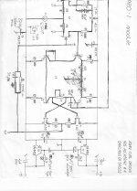
Look at this schematic of a discrete op amp made more than 35 years ago:
NOTE the crossing out of the AC distortion cancellation circuit in the middle of the schematic. The HIRATA test showed me that this added feature generated Hirata distortion, and removing it eliminated any Hirata distortion, although the sine wave or IM distortion was then slightly higher. That is what I might call an 'exotic' or 'advanced' measurement, and this is what I want to concentrate on in future.
Attachments
BTW For those unfamiliar with the Hirata stuff, it's on my website: http://www.linearaudio.nl/linearaudio.nl/index.php/my-library/on-measurement-methods-techniques
Jan
Jan
Last edited:
It's an interesting proposal. What would you see at the output? You would see the 'normal' sinewave load current, offset with a DC output current. So you can have the same effect by using a 'normal' (ac coupled if needed) symmetrical sinewave signal but return the speaker not to ground but to a pos or neg power supply to have the DC current.
So this little thought experiment seems to say that an asymmetric signal would offset the zero crossing. Interestingly, that's what class XD (xover displacement), developed by Doug Self, is all about. You still have the crossover distortion but now at a higher (non-zero) signal level so relatively it is smaller.
But I digress.
Jan
Yessss... I'm thinking... I have the XD patent details to refer too, but I've always thought of the principle as being similar to biasing say an opamp to class A with an external source/sink and with Dougs class XD just making that a variable.
I'm not totally convinced tbh, because I thought of what happens with a single rail amp and how that always has the signal "offset" and riding on some DC value, and you can vary that "offset" or midpoint voltage but its not quite the same as I had in mind.
I've yet to take in Johns article... definitely one for tomorrow.
No response from anyone? It is not just this 'exotic distortion' that we have to test for, but it is a good example. Once I knew what to avoid, I didn't have to make Hirata tests, but trust me, many other amps and preamps would measure badly. This gives me a design 'edge' that started 40 years ago. If you want to be a champion of audio design, you must take these sorts of distortions into consideration.
but trust me, many other amps and preamps would measure badly.
Can you name some that aren't decades old?
From taking a quick read of the pdf at the end the distortion display . The deviation from linear look a lot like some displays of some caps I and others have tested. Thanks again for your insight .No response from anyone? It is not just this 'exotic distortion' that we have to test for, but it is a good example. Once I knew what to avoid, I didn't have to make Hirata tests, but trust me, many other amps and preamps would measure badly. This gives me a design 'edge' that started 40 years ago. If you want to be a champion of audio design, you must take these sorts of distortions into consideration.
I haven't measured any recent pre or power amps from other manufacturers. But, I bet some of them have real Hirata problems.
How would you know this?
- Status
- Not open for further replies.
- Home
- Member Areas
- The Lounge
- John Curl's Blowtorch preamplifier part II