For John or anyone else versed in Feedback theory. What would happen if we took a third wire back to the speaker terminal and used this as the end point of the feedback loop for a power amplifier, the end point of the gnf point that was used to feed the input node? This would include all wire parasitic value and would get you to the point where you would see the back emf coming from the speaker terminal. Would this have any advantage over the current method of leaving the speaker node out of the feedback loop?
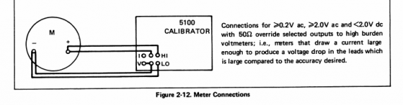
The usual term for this is remote sensing (I'm surprised no one has pointed this out yet). its often done with high power DC power supplies. Its also standard practice with precision AC calibrators. Below is an illustration from the Fluke 5100 manual. its not that exotic or rare, just not normally necessary. Cello also attempted this in some of their products.
Attachments
A,wwayne,
Well the speakers I am working on isn't a ribbon but it does match the impedance curve like I am talking about. I know it isn't the only one in the world and it is a moving coil direct radiator, the Faraday sleeve and long magnetic gap with underhung voicecoil has a lot to do with it.
Well the speakers I am working on isn't a ribbon but it does match the impedance curve like I am talking about. I know it isn't the only one in the world and it is a moving coil direct radiator, the Faraday sleeve and long magnetic gap with underhung voicecoil has a lot to do with it.
Demian,
I hear a lot about this being tried by more than one manufacturer but the fact that it isn't being used I guess means it isn't a successful implementation with speakers and amps. I wasn't looking for a servo controlled speaker so a second voicecoil isn't anything I was looking for. Just was wondering if the speaker emf could be partially controlled this way and the speaker brought into the feedback loop.
I hear a lot about this being tried by more than one manufacturer but the fact that it isn't being used I guess means it isn't a successful implementation with speakers and amps. I wasn't looking for a servo controlled speaker so a second voicecoil isn't anything I was looking for. Just was wondering if the speaker emf could be partially controlled this way and the speaker brought into the feedback loop.
Demian,
I hear a lot about this being tried by more than one manufacturer but the fact that it isn't being used I guess means it isn't a successful implementation with speakers and amps. I wasn't looking for a servo controlled speaker so a second voicecoil isn't anything I was looking for. Just was wondering if the speaker emf could be partially controlled this way and the speaker brought into the feedback loop.
Its hard to implement because you end up with essentially a zero ohm impedance at the sense point and you can easily run out of phase margin with a reactive load. The calibrators all have effective current sensing disconnects to protect them. Mine will work with 10' cables for both sense and drive pretty well as long as the load isn't too low Z. Above 100 KHz it bypasses the remote sensing.
Back emf sensing works well but isn't a universal application thing to do. You need to optimize it for your system. I have done back emf sensing and servo control on woofers with great success (Entec) but that was a closed system.
The usual term for this is remote sensing (I'm surprised no one has pointed this out yet). its often done with high power DC power supplies. Its also standard practice with precision AC calibrators. Below is an illustration from the Fluke 5100 manual. its not that exotic or rare, just not normally necessary. Cello also attempted this in some of their products.
I didn't mention it assuming this was common knowledge. I use it also as an option in the superreg I designed for diyaudio's store.
Jan
Demian,
Thanks for the information. I am not anywhere near capable of designing that type of circuit. My application would be a closed system as it is a self powered speaker, just not sure what degree of improvement this would even bring to the entire speaker system. My question was out of curiosity at first and how it would work. I have gotten a lot of information already about different approaches to the problem.
Thanks for the information. I am not anywhere near capable of designing that type of circuit. My application would be a closed system as it is a self powered speaker, just not sure what degree of improvement this would even bring to the entire speaker system. My question was out of curiosity at first and how it would work. I have gotten a lot of information already about different approaches to the problem.
Stability can be had if you transition to local (as opposed to remote) feedback at RF. Most amps will require an L//R between the feedback point and speaker to snub series resonances, which are an Achilles' heel of voltage-output amplifiers. Ironically, this network may have more impedance than the cable itself.
An amp can be designed to not need the L//R, but this is difficult and IME is not a very flexible approach.
But, this is all academic unless you know there is an advantage to remote feedback. We don't know whether the distortions at the end of the cable are adding to or subtracting from the actual distortions of the loudspeaker, so I would only use remote feedback if there was a known accurate motional feedback source.
I hear a lot about this being tried by more than one manufacturer but the fact that it isn't being used I guess means it isn't a successful implementation with speakers and amps.
The Kenwood amps worked fine. It's just that there's no real advantage to it unless you have very long wires and/or very pathological speakers. Two sets of extra cabling to get a few hundredths of a dB of improvement in frequency response just doesn't seem worth it to most people.
An old/simple design, but ETI 480 is quoted as unconditionally stable, and does not need/use series output network.An amp can be designed to not need the L//R, but this is difficult and IME is not a very flexible approach.
In some testing many years ago, I/we found that typical materials/geometry fig 8 cables introduce 2nd harmonic, due to, we surmised/theorised, motor action between the two conductors....... We don't know whether the distortions at the end of the cable are adding to or subtracting from the actual distortions of the loudspeaker, so I would only use remote feedback if there was a known accurate motional feedback source.
Dan.
Last edited:
I would not suspect motor action between the conductors. The forces on the individual conductors as a consequence of the magnetic fields is rather small in comparison to the modulus of the plastic in figure 8 cables.In some testing many years ago, I/we found that typical materials/geometry fig 8 cables introduce 2nd harmonic, due to, we surmised/theorised, motor action between the two conductors.
Dan.
Proximity effect, on the other hand, is related to the slew rate of the current within the cable. It will modulate the effective cross section of the conductor's current section, so change the resistive drop as a function of slew.
I would love to examine the test setup and data if you have it available. But it sounds like some nice work..
John
An old/simple design, but ETI 480 is quoted as unconditionally stable, and does not need/use series output network.
In some testing many years ago, I/we found that typical materials/geometry fig 8 cables introduce 2nd harmonic, due to, we surmised/theorised, motor action between the two conductors.
Dan.
I was curious and went looking for a schematic...
Lack of an output inductor in the ETI-480 should definitely be
corrected in practice. All amplifiers should include such an inductor, as
load capacitance contributes additional lag phase shift to the overall
negative feedback.
I forget the exact details now...big handful of big PP caps in parallel......DC on cable....able to pull out (discriminate) a modulation.I would not suspect motor action between the conductors. The forces on the individual conductors as a consequence of the magnetic fields is rather small in comparison to the modulus of the plastic in figure 8 cables.
Proximity effect, on the other hand, is related to the slew rate of the current within the cable. It will modulate the effective cross section of the conductor's current section, so change the resistive drop as a function of slew.
I would love to examine the test setup and data if you have it available. But it sounds like some nice work..
John
Dan.
IIRC, the unconditional bit was in the original magazine article....perhaps I am wrong ?.I was curious and went looking for a schematic...
Anyway, 30+ years ago I built two of those modules into a junked Jap integrated amp, but used (then) good Jap flatpack output transistors instead of the specified 2N3055/2N2955.
I did some tweaking (cap and resistor types) and the result was happily stable, sounded bloody good, and did a million parties.
Not ppm THD, but very happily musical with good power supply arrangements and wiring techniques.
Dan.
I'm confused now (true, the bar is low..)I forget the exact details now...big handful of big PP caps in parallel......DC on cable....able to pull out (discriminate) a modulation.
Dan.

I do not know what the second harmonic of DC is.
jn
A Monty Python fan stirring the pot has made things worse.
That’s me, right?
Welcome back Ed. I started worrying…It has been done using a feedback coax with BNC connections. Didn't improve things for an obvious reason that most folks miss. The loudspeaker was voiced using a regular amplifier.
What is this 'obvious' reason (apart from the Pavel’s mentioned picked-up noise and jn points in his #50092 post)?
Now for the peanut gallery a couple of simple questions:
What is the maximum output voltage of a compliant CD player?
Commonly 2Vrms but I've measured almost double as this.
What is the minimum input impedance of an IEC compliant consumer amplifier/preamplifier?
~2.2k but today ~4.5k
Headroom ?What is the typical headroom when playing a listening test or high quality CD?
You mean the crest factor of the recording?
The headroom at the preamplifier input, implying input overload?
The headroom at the amp out implying dynamic compression and or clipping?
Allowing for the above what is the typical current in an interconnect cable?
0.5mA max
No Bad Cable. Bode stability criterion.
Pavel and all
I ask for your theoretical knowledge and practical experience with that one.
Say an amplifier has it’s output HF oscillating (forgive the loose term for now).
My question is, what determines the frequency at which it oscillates.
1. The design of the amplifier, i.e. unit bandwidth, phase margin ?
2. The above in combination with C, R of the load (cable, speaker)?
3. The 1/2L, 1/4L of the unterminated speaker cable?
George
Last edited:
Thank youLong time ago.
In the next few weeks I can revisit the experimenter/experiment and give you better details.
The 2nd harmonic was of the exciting signal, DC bias was on the cable....I think.
Dan.
John
- Status
- Not open for further replies.
- Home
- Member Areas
- The Lounge
- John Curl's Blowtorch preamplifier part II