For most practical purposes a 2W 100 Ohm resistor will work. While I have not tried formal double blind tests its usually a pretty obvious improvement (change). If you have something like Cobra cable or Analysis plus (or another really low Z cable) you will need to figure it out. One way is to drive the cable with a fast rise pulse watching with a scope and trying different values until the reflection is gone. This won't be correct for audio frequencies but at audio frequencies the cables' impedance is less of an issue than its lumped R, L & C.
What is the value of the resistor?
180 ohm. It is not very critical. It should be something like characteristic impedance of the cable, but for cables of this kind (zip cord like) values 100 - 300 ohm are fine.
JN has correctly described the effect, one can measure it with a scope as a decrease of HF mess or improved step waveform transfer (both is true).
As should be the output impedance of the source .....
... which is impossible here. But even cable terminated at the beginning or at the end behaves much better than the cable driven from zero impedance and open at the end. And this is approximately power amp situation, cable is driven from low output power amp impedance and inductive character of speaker box impedance at high frequencies makes it open at the end. The only place where to put it, in the real world application, is the end of the speaker cable.
Conventional engineers, working for a wage, will never deliver top notch audio. All they worry about is meeting the 'requirements', a few measurements on the 'right' instruments - a good set of numbers - and they're happy ...
This is a game that still requires genuine passion to get anywhere - a brilliant, but bored engineer will serve up Yet Another ho-hum product ...
Don't work with many engineers! Its rather a generalisation. They are often frustrated by the limitations put on them. For high end audio though I see more effort often put in the marketing rather than the parts and construction. And mid range quite often from what I've seen of the insides it designed to some very strict cost factors. Same with PC motherboards, when we do a 'PC' type circuit for high end equipment we will use 14-16 layers, a mother board will have 6-8, basically the same circuit, the only difference is we will strive to run all critical signals stripline between two ground planes, hence the extra layers ( and much reduced noise). Same for sensitive analogue, 6-8 layers instead of 2-4.
Some PCB impedance calculators.
http://emclab.mst.edu/pcbtlc2/
http://www.technick.net/public/code/cp_dpage.php?aiocp_dp=util_pcb_imp_calculator
Last edited:
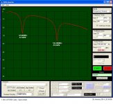
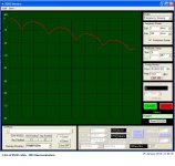
This is with coaxial RG58 cable.
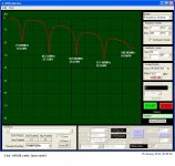
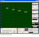
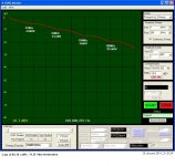
See the resonances as seen at generator-out due to reflections at the cable end and the effect of resistive termination at cable end.
Generator's nominal Output impedance 50 Ohm
George
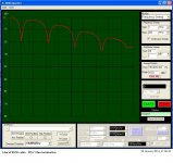
See the resonances as seen at generator-out due to reflections at the cable end and the effect of resistive termination at cable end.
Generator's nominal Output impedance 50 Ohm
George
Attachments
-
 1 1.18m RG58 Open-Ended.JPG100.3 KB · Views: 241
 -
 2 2.4m of RG58 Open-Ended.JPG106.7 KB · Views: 231
 -
 3 2.4m of RGB58 10 Ohm termination.JPG105 KB · Views: 235
 -
 4 2.4m of RG58 51.24 Ohm termination.JPG102.5 KB · Views: 221
 -
 5 2.4m of RG58 cable 100.06 Ohm termination.JPG98.8 KB · Views: 211
 -
 6 2.4m of RG58 cable 200 Ohm termination.JPG103.1 KB · Views: 86
 -
 7 2.4m of RG58 cable 508.7 Ohm termination.JPG97.5 KB · Views: 81
 -
 8 2.4m of RG58 cable 999.7 Ohm termination.JPG99.6 KB · Views: 73
 -
 9 2.4m of RG58 cable 1996.8 Ohm termination.JPG99.6 KB · Views: 76
 -
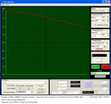 10 Baseline of 1MHz-200MHz Freq Sweep.JPG105.6 KB · Views: 82
Last edited:
True PMA, some high end stuff I respect and like, but some leaves me wondering where the money goes. My main despair is with some of the mid range stuff, but that is becoming the norm with a lot of electronics, people want fashion items at a low price and bin them in a year when the next bigger better model comes out. We work on both ends of the spectrum, designs where quality comes first and cost to an extent is secondary, and designs where we have to cut every last penny off a design.
Yep. Correct.George, try to put a divider like 50/5 ohm to the generator output. Then you will drive the cable from <5 ohm impedance. You will get gross impedance mismatch. Then the effect of the terminating resistor will be even much more pronounced.
I’ve done it as I am working on the issue.
Jn has put me on fire and I am in the preliminary steps.
I will start a thread, I will post a link when I am ready.
Thanks again.
George
>Edit:The pics above is just to show the effect of termination and the shifting down in freq of the resonances as the length of the cable increases
Last edited:
Here are the equations:
Ah, thanks! Looking from the equations I can see that producers are actually free to choose the impedance for their cables (no cost boundary). So is that any optimum value? Also, Teflon has epsilon of 2.1 which is not a unique value, so why expensive cables use it?
Ah, thanks! Looking from the equations I can see that producers are actually free to choose the impedance for their cables (no cost boundary). So is that any optimum value? Also, Teflon has epsilon of 2.1 which is not a unique value, so why expensive cables use it?
It is used as a lubricant to help slide the money out of full wallets.
- Status
- Not open for further replies.
- Home
- Member Areas
- The Lounge
- John Curl's Blowtorch preamplifier part II