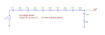
Holy cow! THAT is quite a statement for 'just' a 1st stage!Here is an example circuit, exotic enough for you? This is ONLY an example. It will not necessarily work as shown.

It probably requires a lot of man-hours and pile of parts to put than one together..
The DA stuff there is mostly nonsense.
It is not a nonsense. Please check the attached image. Sometimes high voltage dividers are designed this way. Try, after some time, like days, weeks, to measure DC voltage across capacitors. You will find that some have higher residual DC, some lower, some positive and some negative. This is DA in real world and discharge resistors of high value must be used over every capacitor of the series damped capacitive voltage divider.
Attachments
It is not a nonsense.
Pavel
Scott has worked on DA in the past (see below). His ‘nonsense’ now refers to the DA ‘cross-over distortion’
That's something that came up here between Earl Geddes and me a couple years ago. When the measurements were made, nope, no sign of "zero crossing." It makes no physical sense for there to be one, but it was easy to check.
SY
I searched for the mentioned test but I didn’t find it (I found a few posts from the usual suspects that shed some light but not the specific test and no Earl Geddes)
George
Now, back again to the phono design. This design is the rough equivalent to a Bentley in the auto world. Big, powerful, effortless, remote controlled, and expensive. This is for the very wealthy or at least committed to the best that audio can be. It is impractical for the rest of us.
George, thanks for the clarification. Cross-over distortion based on DA is really highly improbable.
There is also plenty of technical sloppyness like "absorbing some of the AC energy". When John, Walt, and I worked on this I pointed out that all but the most horrible capacitors fit a Pease R/C ladder model very well. He used it to compensate integrating A/D's to an, at the time, SOTA accuracy. This was engineering not folklore. As time went on the reality was just too boring I guess, and the memory, "echos", etc. stuff crept back in.
Making up lies. Wow! Who knew? '-)
Yup. The statements that I am only a theorist is fightin words.
Half of what I do is theory. The other half is building and testing. building and testing some very strange things.
Your new to this town, aint'cha..JN
PM me a shipping address. I will send you a few coils to measure so we can compare notes. I think you are drifting off the issue of disagreement.
We both understand there is more than one issue affecting signals in a cable. The issue is inductance and if it changes in a coiled cable.
So inductance bridges at high noon, stranger!
ES
The cable coiled inductance measure is a dead horse Ed.
However, measurement of proximity effects on twisted pair cables is a really good topic. As you've an AP, perhaps we can get together on some precise test setups to provide all some nice guidelines for using twisted pair cables.
I've seen articles on that problem before, but I've never had to worry about it. I do have issues with weave directionality with respect to thermal expansion coefficients. G-10 for example, has a sinusoidally varying TCE in the plane of the weave, but a higher one normal to the weave planes.Interesting article here about PCB material and very high data rates. One for JN and the physicists here to get their teeth into I guess!
Glass weave skew problems may be solved | EDN
Excellent test, thank you. I agree with you that your layout does not alter separation.I have made one more channel separation measurement, especially for JN. Now, the whole chain of Preamplifier + PA4 power amplifier was measured. With cables and everything, of course. Then, a measurement of Preamplifier alone was done. One may see that the power amplifier has not changed the measurement result! Finally, as a reminder, channel separation of power amplifier PA4 alone is shown. The conclusion is that it is a preamp that defines channel separation, in case that power amplifier has a proper dual-mono layout and proper wiring.
It is unfortunate that your results cannot be applied to all amps and all preamps out there. I wish there were an industry standard.
Would you care to discuss measurement of ground loop current sensitivity?
Yup. I do not recall "measurements", just that it was beddy beddy bad.Ed, I don't have the energy right now but I distinctly remember you stating that someone left the wire coiled and his measurements were "all wrong" implying that uncoiled would have been OK.
If there is sufficient capacitance to ground somewhere, that could enhance rf intrusion. You may have hit on the actual cause..who knows..Since I started this coiled mic tangent . Some important field data does come to mind. Cincinnati music hall where the event happened is in a strong FM field about 1.5 to 1.8 volts rf in the house at 90.9 mhz . the coil was at least 250 feet if I remember correctly . Though I will not disagree with the theory that a coiled mic cable should not have added inductance what if the helical coil as an antenna for strong fm signal. When we take thing out of context the wrong conclusion . In this case the coil acting like an antenna in a strong RF field may have been injecting that RF in the system . When the antenna was detuned the interference was reduced . So a small increase in inductance in and of itself being measured small could have caused a problem not proximal circuit designed. Look forward to you view on that limited possible cause.
I use a stereoscope for all my stuff, my eyes ain't what they used to be..My tech, just yesterday, borrowed my 'stereo microscope' to do some SMD work. Perhaps I should get some new hand tools, but I can do just fine without SMD, for the most part.
Funny you mentioned copper bars , I'm experimenting with flat 1/2 inch wide copper wire to connect to the amplifier , im pretty impressed with the sound i have the conductors spaced 1 inch apart i will do another pr at 1/2 and compare...
i can give you measured data or i can also report my subjective findings. Before i went for heavy gauge round and it did not work , this works much better , its not used on the bass , its used on the mid/ high ribbon drivers ..
I may drag it in one day and measure RLC , my rig only measures up to 40k ...
Like the Nordost Valhalla?The copper foil is physically locked in , flat ,( similar to a ribbon cable) on mylar , they seperate at point of connection.
I measured 1/2 inch copper spaced on a film as well as with a film between them. The effect of the foil side by side is to increase the reluctance path, lowering the self inductance. I measured the two geometries, I'll try to find the graphs...edit:found them.
Given a 1 or 2 ohm load, I'd be more inclined to drop the cable impedance down into the 4 to 8 ohm region to reduce the inherent line delay in a high z line with low z terminations at both ends.
There is the Earth's magnetic field, and current flowing in the wire.
yup. Half gauss fields, sometimes as much as .7 gauss. Nowhere near enough field to cause current to divert within a conductor.Put some numbers on that, jn would.
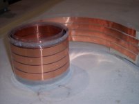
edit: here's a pic of the valhalla clone I made a while back using half inch copper 3 mils thick. (.003 inches). Also, the test data for this as well as the same half inch wide foil one on top of the other, with a 3 mil kapton insulation between. The measurement of the wide spacing falls apart at the higher frequencies, that is why I do a frequency scan with all inductance measurements, to make sure the equipment is behaving..given the low capacitance of the clone, I suspect either the cable is broadcasting into free air, or the length is setting up a t-line resonance which the meter is mis-interpreting.
edit:sorry, can't find a pic of the 8 ohm cable.
jn
Attachments
Last edited:
Do we REALLY have to debate Dielectric Absorption again?
I must admit that I missed its significance in the '70's. A friend of mine actually sent me his masters thesis on DA in 1974, and I completely missed its relevance to audio at the time.
It was Richard Marsh who got the ball rolling on DA. Then Walt Jung's and Richard Marsh's paper 1980 paper in Audio got me to take it seriously.
Then Walt and Scott Wurcer devised a test that made making RELATIVE measurements of DA both interesting and repeatable. The only problem with this test was that it was difficult to interpret WHAT DA actually did to the audio signal over time, but it was exciting to test virtually every type of capacitor and sort them out with this test.
Scott, even did a SIMULATION of the cap test in SPICE, and it gave virtually the same results as the real thing. However, Richard did not like the test as much, and he did not want to do a paper with us on DA using this test. He wanted a more elaborate test to truly show what DA does, so Walt and I wrote a short paper on it.
Of COURSE, there was controversy. And so it goes!
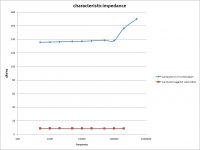
Frequency scale on graph? There are numbers but no units.jneutron said:here's a pic of the valhalla clone I made a while back
SY
I searched for the mentioned test but I didn’t find it (I found a few posts from the usual suspects that shed some light but not the specific test and no Earl Geddes)
http://www.diyaudio.com/forums/multi-way/124824-electrolytics-sound-fine-3.html
Start with post 62. This was with electrolytics; polymer dielectrics have more linear polarizability.
http://lamsimenterprises.com/Practical_Fiber_Weave_Modeling_Iss3_Mar2_12.pdf
Some more on PCB weave, though I don't think it would have any effect at Audio frequencies, and with digital when you get to the speeds where it could be a problem, you are usually moving onto more exotic dialectics anyway. Me I worry more over the roughness of the copper on the non rolled side
Some more on PCB weave, though I don't think it would have any effect at Audio frequencies, and with digital when you get to the speeds where it could be a problem, you are usually moving onto more exotic dialectics anyway. Me I worry more over the roughness of the copper on the non rolled side
Frequency scale on graph? There are numbers but no units.
Hz
George
Edit: Thank you SY. I will go on reading.
Last edited:
I rarely use an electrolytic coupling cap, although there are a few types that work pretty well with a little DC bias on them.
I would NEVER use an electrolytic cap in an speaker crossover. Even the electrolytic caps made specifically for speaker crossover service can have amazing levels of DA and harmonic distortion too!
I would NEVER use an electrolytic cap in an speaker crossover. Even the electrolytic caps made specifically for speaker crossover service can have amazing levels of DA and harmonic distortion too!
Measuring a resistive characteristic impedance below 1000Hz in a cable which is likely to have particularly low inductance looks a bit suspect, but I could be wrong. How was the measurement performed? The variation at the HF end looks to start rather earlier than I would expect - unless this balanced cable was being driven unbalanced and so began to act as an antenna.
Measuring a resistive characteristic impedance below 1000Hz in a cable which is likely to have particularly low inductance looks a bit suspect, but I could be wrong. How was the measurement performed? The variation at the HF end looks to start rather earlier than I would expect - unless this balanced cable was being driven unbalanced and so began to act as an antenna.
I am also curious, at very small portions of a wavelength is it sufficient to measure L/C and compute Z? BTW I get ~.0025 Ohms/ft R if that picture is 4-1/2" stripes in parallel. Folks have tried 6-RG58 in parallel go for 50?
Last edited:
The inductance measurement was performed very well..Measuring a resistive characteristic impedance below 1000Hz in a cable which is likely to have particularly low inductance looks a bit suspect, but I could be wrong. How was the measurement performed?
Actually, if the low frequency inductance did something different, then I'd be suspicious. As it flatlined down to 500 hz with no anomalies, I've no concern as to the validity of L down to 500 hz in this case.
Care must be taken when measuring inductances in the 50 to 100 nH range, as the setup lead issues can be non-trivial. When I work low inductance, I physically setup the leads and DUT, and do a zerocal with a shorting wire directly across the DUT at the connection. Any movement of the test leads at the DUT require re-zeroing, as simple movement of the leads can be several times larger than the measure.
The graph is simply z = sqr(L/C). As such, it ignores the distributed R and G.
As measurement of energy storage within the cable at audio frequencies, it is enough information. It shows that capacitance as well as inductance measurements were consistent.
As a measurement of settling time for a sub wavelength t-line terminated at each end with terribly low impedance, it can only provide a minimum settling time. The actual z at audio frequencies will be higher by a factor of 2 to 4, and the prop velocity will also be quite slower. So calculation of final settling time at audio can just be assumed at least 2 to 4 times slower.
I run L and C through a wide range of frequencies in order to assure myself that the equipment is behaving well.
It is a roughly 10 foot long two conductor system with 1.5 inch spacing. Because the capacitance was very low, I would not expect a bulk resonance at 200Khz, and the line length is also too short for resonance via t-line reflections. So as I stated, I believe it may have been broadcasting. I made sure there were no conductive objects near the cable during measurement.The variation at the HF end looks to start rather earlier than I would expect - unless this balanced cable was being driven unbalanced and so began to act as an antenna.
jn
Last edited:
- Status
- Not open for further replies.
- Home
- Member Areas
- The Lounge
- John Curl's Blowtorch preamplifier part II