EMC receptivity is but one aspect affecting audio gear. A very important one, but not the only one.
(On my A/V gear I have 4 different power isolation transformers).
EMC is also affecting your precious hearing system, this is something that is sorely missing from the current medical body of knowledge. Until medical scientists will decide to fill in the gaps, have you considered wearing a tin foil crest during your listening tests?
Seriously, the secret of your audio happiness is not in the physics and electronics theory, which you are so dearly fighting with, but in understanding the physiology and mechanisms of your hearing.
The rest is reiterating "We don't need no education..." which is, unfortunately, not even an original stance.
…
The clue, as I see it, is how the low level distortion manifests
…
This is but one important aspect that should be measured.
EMC is also affecting your precious hearing system, this is something that is sorely missing from the current medical body of knowledge. Until medical scientists will decide to fill in the gaps, have you considered wearing a tin foil crest during your listening tests?
Seriously, the secret of your audio happiness is not in the physics and electronics theory, which you are so dearly fighting with, but in understanding the physiology and mechanisms of your hearing.
The rest is reiterating "We don't need no education..." which is, unfortunately, not even an original stance.
As long as you are satisfied with whatever you are doing, all is well.
Why I specifically note that is because it correlates beautifully with the subjective impression of the playback - it clearly stands out as being a metric of 'good' sound, for me at least.This is but one important aspect that should be measured.
Very easy to 'measure': high quality sound, at high SPLs, allows you to move your ear very close to the tweeter, or driver handling the upper part of the spectrum; and it still sounds clean, there is no abrasive, unpleasant quality about it. Typical playback is a long way from this, the sound from the tweeter is exceedingly unpleasant, even offensive, at close quarters -- that's the distortion that's "mucking" up the sound ...
Why I specifically note that is because it correlates beautifully with the subjective impression of the playback - it clearly stands out as being a metric of 'good' sound, for me at least.
Very easy to 'measure': high quality sound, at high SPLs, allows you to move your ear very close to the tweeter, or driver handling the upper part of the spectrum; and it still sounds clean, there is no abrasive, unpleasant quality about it. Typical playback is a long way from this, the sound from the tweeter is exceedingly unpleasant, even offensive, at close quarters -- that's the distortion that's "mucking" up the sound ...
")
I must agree on the view of EMC, with power line communications (should be banned) mobile devices and mobile internet everywhere, the requirements for more intense EMC testing are needed. This is happening in some areas of electronics, but not really in consumer goods. Along with this is a requirement for more EMC protection on board, careful layout (some RF techniques required), multilayer PCBs etc, all this adds cost!
Also when you look around DIY projects, there are very few that have EMC protection circuitry? Some even claim that as it is DIY they don't have to bother with EMC.
As I have said before, EMC and Signal Integrity are two sides of the same coin, you have to be concerned with both to get the best system.
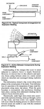
Certainly one way to do it. The only caution I have is that the wires near the bond be supported with a damping material during the energy transfer. If the wire outside the weld is not supported during the weld, they may flex out of control and be damaged. This should be evident by high power examination of the surfaces of the wire. Damage will show up as slip plane dislocation at the surface, this can be seen as a rough surface. At high magnification, you can see lines.
jn
I have no hands on experience with UT welding.
Your concern sounds logical but the energy applied is relative low and well focused.
The massive dislocation of crystals outside the spot would require much more energy. I had a look in a book for such a distortion and it matches another welding method (att. 1)
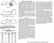
Another possibility is simple pulse welding, like a millifarad cap charged to voltage, then discharged across the two conductors being held in compression. I evaluated a stud bonder back in the late 80's, it could weld a 6-32 or 8-32 stud directly to a metal surface. I don't recall if it used a relay or active switches to provide the current pulse.
On one unit I had seen, the cap bank discharge (switching action through a fast acting relay) was driven to the primary of a step-down transformer, the welding electrodes were connected to the secondary (Vsec~50V)
Some info on this (att.2)
George
Attachments
Last edited:
Amen!I must agree on the view of EMC, with power line communications (should be banned) <snip>
As I have said before, EMC and Signal Integrity are two sides of the same coin, you have to be concerned with both to get the best system.
something that is sorely missing from the current medical body of knowledge.
Ever heard of the Frey effect ?
(all in all, you're just another brick in the wall)
Good equipment design can minimise this problem. Also avoiding strange expensive 'audiophile' cables.Joshua_G said:It's impossible to cancel the interaction between the source output impedance, the target input impedance and the connecting cable impedance - over the entire frequency range of interest - and the receptivity or immunity of cables to picking up external EMI, including in the RF range - when attached to certain gear and terminated by it.
Two groups of people have a THD fixation:fas42 said:the THD fixation has demonstrated itself totally meaningless;
1. audio marketeers,
2. THD-haters.
Everyone else just treats it for what it is: a single piece of information which tells us something but not very much.
a single piece of information which tells us something but not very much.
A single number tells little, a complete picture talks a thousand words.
(Similar to automobile data, single numbers for horsepower/torque/top speed/0-60 acceleration are worth JS, while detailed figures over the entire speed/rpm range are solid gold. Unfortunately, non-technical minded are not interested in other than short and simple)
You seem to be considering EMC as the interaction between external influences and the signal integrity within the equipment.It may be applicable also to other tests, not only EMC.
I go much farther with my EMC.
1. External time varying magnetic fields (Bdot) which are trapped by conductive loops of the interconnects and power cables.
2. Internal Bdot fields caused by the line wires, the transformer, supply caps, power supply rails, and the path ground loop currents take within the chassis.
3. External Bdot created by the internal workings of the equipment. For example, the power transformer stray fields may actually loop around the ground loop path, so amp power draw can cause ground loop currents external to the amplifier, through the IC's. Also, the haversine currents of the power draw, in addition to the actual music content bleeding through into the line cord, modulated at 120 hz by the diode conduction duty cycle of course..
Of these, 1 and 3 cannot be bench evaluated, they are accentuated by the in situ connections.
2 can be bench tested, but the effects may not be properly considered by current bench methodology.
Would be an interesting DIY project ...
As long as the caps don't blow up during discharge..
I do have hands on experience. The energy required to weld will indeed be a significant amount with respect to high cycle fatigue flexure to failure close to the weld. I recommended the visual because I have used visual as an indicator of fixturing weakness with respect to protecting the wires near the weld. When my presence was requested across the pond for their soldering problems, I also detailed to them their U/S welding failures, why they occurred, how to correct the fixturing, and how to visually examine the joints for U/S flexure failure problems.I have no hands on experience with UT welding.
Your concern sounds logical but the energy applied is relative low and well focused.
The massive dislocation of crystals outside the spot would require much more energy.
Nice links, thanks..
On one unit I had seen, the cap bank discharge (switching action through a fast acting relay) was driven to the primary of a step-down transformer, the welding electrodes were connected to the secondary (Vsec~50V)
Some info on this (att.2)
George
In my mil hybrid days, they would create the ceramic pcb by successive firings of non conductive glass and patterned gold filled glass. On occasion, a pinhole would ruin a substrate, so I would use a cap discharge method to blow the offending trace to trace short. Sometimes it wouldn't work, but many substrates were recovered using the technique. AFAIR, this technique was also used to recover shorted NiCad batteries where whiskers had grown to short.
jn
Sadly the non-technical non big picture seers make the most noise about small details that do not effect the outcome and deny those factors that are of importance.A single number tells little, a complete picture talks a thousand words.
(Similar to automobile data, single numbers for horsepower/torque/top speed/0-60 acceleration are worth JS, while detailed figures over the entire speed/rpm range are solid gold. Unfortunately, non-technical minded are not interested in other than short and simple)
Why I specifically note that is because it correlates beautifully with the subjective impression of the playback - it clearly stands out as being a metric of 'good' sound, for me at least.
...
Indeed, though probably low level distortion isn't the only thing that in itself ensures high degree of realism in music reproduction.
…
EMC and Signal Integrity are two sides of the same coin, you have to be concerned with both to get the best system.
Indeed, though there are other factors, besides EMC, that affects the degree of realism in music reproduction.
Good equipment design can minimise this problem. Also avoiding strange expensive 'audiophile' cables.
I don't know what 'good equipment' is.
My power amp is Pass Labs XA 30.5, my CDP is AMR CD-777.
Both benefit from power isolation transformers and good cables (power cord and interconnect).
I haven't encountered yet equipment that does not benefit from the above.
Two groups of people have a THD fixation:
1. audio marketeers,
2. THD-haters.
Everyone else just treats it for what it is: a single piece of information which tells us something but not very much.
Indeed.
A single number tells little, a complete picture talks a thousand words.
Indeed.
However, I didn't see so far a set of measurements that gives the complete picture, concerning the degree of realism in sound reproduction.
You seem to be considering EMC as the interaction between external influences and the signal integrity within the equipment.
I go much farther with my EMC.
1. External time varying magnetic fields (Bdot) which are trapped by conductive loops of the interconnects and power cables.
2. Internal Bdot fields caused by the line wires, the transformer, supply caps, power supply rails, and the path ground loop currents take within the chassis.
3. External Bdot created by the internal workings of the equipment. For example, the power transformer stray fields may actually loop around the ground loop path, so amp power draw can cause ground loop currents external to the amplifier, through the IC's. Also, the haversine currents of the power draw, in addition to the actual music content bleeding through into the line cord, modulated at 120 hz by the diode conduction duty cycle of course..
Of these, 1 and 3 cannot be bench evaluated, they are accentuated by the in situ connections.
2 can be bench tested, but the effects may not be properly considered by current bench methodology.
…
Indeed.
Sadly the non-technical non big picture seers make the most noise about small details that do not effect the outcome and deny those factors that are of importance.
What are those factors that are important?
What make the big picture?
At a PCB manufacturer in town here, who emphasized their quality and high technology, I was given a tour. One after another room with about everything one could imagine, a lab with some very fancy inspection equipment, on it went. Finally a room full of fixturing for board testing for continuity and shorts. On the floor was a 12V lead-acid battery, which was used to clear shorts they couldn't see. Things seemed suddenly much more down-to-earth at that point.In my mil hybrid days, they would create the ceramic pcb by successive firings of non conductive glass and patterned gold filled glass. On occasion, a pinhole would ruin a substrate, so I would use a cap discharge method to blow the offending trace to trace short. Sometimes it wouldn't work, but many substrates were recovered using the technique. AFAIR, this technique was also used to recover shorted NiCad batteries where whiskers had grown to short.
jn
I don't know what 'good equipment' is.
The comments write themselves.
Indeed, though there are other factors, besides EMC, that affects the degree of realism in music reproduction.
Noise are one of the affecting factors..
Have you tested the 2SD786 transistors yet?
And what is noise?
It wasn't as daft as it sounds, at least they got a record faults instead of numerous 'no fault found'.
When I was a college, I did a few weeks work experience, where one of the old hands taught me the six inch nail trick for fault finding! If he couldn't find the fault within a certain time he would replace the fuse with a sawn of length of a six inch nail, as he said, if its a bad fault we'll soon find it!!! We were repairing colour monitor scan boards, plenty of fireworks.On the floor was a 12V lead-acid battery, which was used to clear shorts they couldn't see. Things seemed suddenly much more down-to-earth at that point.
It wasn't as daft as it sounds, at least they got a record faults instead of numerous 'no fault found'.
And what is noise?
When I was a college, I did a few weeks work experience, where one of the old hands taught me the six inch nail trick for fault finding! If he couldn't find the fault within a certain time he would replace the fuse with a sawn of length of a six inch nail, as he said, if its a bad fault we'll soon find it!!! We were repairing colour monitor scan boards, plenty of fireworks.
It wasn't as daft as it sounds, at least they got a record faults instead of numerous 'no fault found'.
Isn't that the monitor company that kept losing business so started a sideline folding parachutes??
jn
Hi Joshua, yes, it is almost impossible to find 'good equipment' in audio. By that definition, I mean, completely EMI proof, so that external line filtering would not be helpful. Everything that I own or make has benefited from power line filtering. However, the worst example that I have found is my STAX vacuum tube headphone amp. Go figure!
- Status
- Not open for further replies.
- Home
- Member Areas
- The Lounge
- John Curl's Blowtorch preamplifier part II