No acoustic coupling.
What I am saying is that any delay of part of the frequency content of a stereophonic signal can shift the perceived image. It requires a central image in the field upon which a human can reference to because head positioning uncertainties will swamp un-referenced positions.
For a monophonic presentation, time delay of part of the spectra can result in a depth change of that part, but never a side shift.
Discussion of audibility requires understanding audibility. Welcome to my world. Please, pull up a seat and stay a while..
edit: my world being one in which I had a long and steep learning curve as well..
cheers, jn
btw, that is one big problem I have found with 11 band eq's...If you dont get both channels exactly symmetrical, it is easy to find that the sibalance of a female vocal is shifted to one side of the fundamental..a disembodiment so to speak..
ps. Please read my content w/rt to hearing several times prior to responding. I've been quite clear in the bulk of my posts, and am spending a lot of effort duplicating verbage.
One of the biggest problems with frequency-dependent channel-channel phase differences lies in the loudspeakers, especially in the crossovers. This is doubly true for all-pass crossovers like the Linkwitz. Passive component tolerances can cause the crossover point in the two channels to be at slightly different frequencies, resulting in significant inter-channel phase differences in the frequency bands near the crossover points.
This is huge compared to any cable-related frequency-dependent differential phase effects.
Cheers,
Bob
Please re-read the last paragraph..
specifically..Don't be thrown off by the units btw, as a simple calculation of a 10Khz square wave energy per lobe will show that the energy levels displayed cannot be brushed aside.
jn
I did, but that red text made it really hard
") .
.Cheers,
Bob
I believe I pointed out the issue with my 11 band eq statement. Glad we agree.One of the biggest problems with frequency-dependent channel-channel phase differences lies in the loudspeakers, especially in the crossovers. This is doubly true for all-pass crossovers like the Linkwitz. Passive component tolerances can cause the crossover point in the two channels to be at slightly different frequencies, resulting in significant inter-channel phase differences in the frequency bands near the crossover points.
This is huge compared to any cable-related frequency-dependent differential phase effects.
Cheers,
Bob
This statement is based on what research? Have you performed any three speaker image reconstruction tests?
Or even the minimal test...use two speakers, one amp channel, three cables 10 feet long each, #12awg all cables, one cable 8 ohms Z, two cables 120 ohms Z.
Connect both 120 ohm cables to one amp channel, other ends to the speakers. Look for image construction in the center while in the sweet spot.
When you are satisfied that the speakers are equal, swap one cable to the 8 ohm.
Repeat looking for the fidelity of the central image.
Don't forget, our localization is really weird in that we tend to "lock" around center in the frequencies of interest despite small changes in ITD and IID. Greisinger shows that clearly in the 600-900 hz range in his graph (incorrectly identified as figure 5, it is really figure 6..)
If you can "see" a shift of some harmonic content away from the bulk of the sounds which did not exist with identical Z cables, you will have some explaining to do, no??
jn
edit: one amp channel is used to eliminate the possibility that one channel reacted differently as a result of the cable capacitance. Elimination of confounders...
Last edited:
I did, but that red text made it really hard
Cheers,
Bob
Yabut...some of the other colors I can't even read...
jn
See attached. Note that the same paper has a graph which takes it out to 12Khz.
For unjittered sine waves, the summary you speak of is consistent with this data. It is about 5 uSec in the 500 to 1000 hz range.
jn
I'm still hung up on where the reference is. I sent one of my ambient recordings to a friend and he commented on the nice imaging/binaural effect of the bird's singing. If he got a "reach out and touch" effect how do either of us know if it matched the physical reality.
Also one could invoke the difference/preference issue yet again.
Last edited:
I was referring to time of flight, not velocity of emitter.
even Rod Elliot figured out the veiwpoints are equivalent - shame he didn't use windowing, fft on his data to extract numbers instead of just leaving it to eyeballs:
Doppler Distortion in loudspeakers
Xmax for mid/woofer? up to 10mm?, 3mm = 10us, some run from 100 Hz to 2 kHz in a 2-way system
Last edited:
esr limits current thru cap -
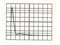
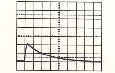
Here are two typical values which are found in cross-overs -- a several mfd. They are same C value and charged to same 5vdc and discharged into themselves-- current monitored [inductive pickup]. The vert scale is 5A/div. The film and foil allows a lot more current to be passed thru itself... compared to electrolytic type construction. So if you calculate the current delivered from power amp to be large, be sure it isnt being limited by unseen series esr from non-film caps. Thx-RNMarsh
[ps - also note the discharge period is then the resolution limit to the circuit]
Attachments
Last edited:
I believe I pointed out the issue with my 11 band eq statement. Glad we agree.
This statement is based on what research? Have you performed any three speaker image reconstruction tests?
Or even the minimal test...use two speakers, one amp channel, three cables 10 feet long each, #12awg all cables, one cable 8 ohms Z, two cables 120 ohms Z.
Connect both 120 ohm cables to one amp channel, other ends to the speakers. Look for image construction in the center while in the sweet spot.
When you are satisfied that the speakers are equal, swap one cable to the 8 ohm.
Repeat looking for the fidelity of the central image.
Don't forget, our localization is really weird in that we tend to "lock" around center in the frequencies of interest despite small changes in ITD and IID. Greisinger shows that clearly in the 600-900 hz range in his graph (incorrectly identified as figure 5, it is really figure 6..)
If you can "see" a shift of some harmonic content away from the bulk of the sounds which did not exist with identical Z cables, you will have some explaining to do, no??
jn
edit: one amp channel is used to eliminate the possibility that one channel reacted differently as a result of the cable capacitance. Elimination of confounders...
Just do the math. The objective measurable/simulatable difference in potential differential phase is huge - no need to do some fancy image reconstruction tests to see that this is obvious. We're probably taking nanoseconds versus microseconds. One measly degree at a crossover frequency of 3kHz is about 1us if I'm not mistaken. It would take perhaps 500 feet of cable length difference to get a microsecond.
Cheers,
Bob
Cheers,
Bob
I'm still hung up on where the reference is. I sent one of my ambient recordings to a friend and he commented on the nice imaging/binaural effect of the bird's singing. If he got a "reach out and touch" effect how do either of us know if it matched the physical reality.
We don't. And, we can't.
It is impossible to recreate the wavefronts of multiple sound generators using two speakers, unless the source being synthesized is at a speaker.
Central imaging is the closest to the exception we can get. But only because of the strength of our response to first arrival.
It is certainly impossible to do so by ignoring interchannel time delays.
Stereo is an attempted synthesis. By invoking some artificially generated IID and ITD, it is possible to fake us into thinking a sound is in a position not occupied by a speaker. Honestly, I'm surprised we can do as much as we can just using IID.
jn
Here are two typical values which are found in cross-overs -- a several mfd. They are same C value and charged to same 5vdc and discharged into themselves-- current monitored [inductive pickup]. The vert scale is 5A/div. The film and foil allows a lot more current to be passed thru itself... So if you calculate the current delivered from power amp to be large, be sure it isnt being limited by unseen series esr from non-film caps. Thx-RNMarsh
[ps - also note the discharge period is then the resolution limit to the circuit]
Agreed, and I don't think there is too much controversy about the wisdom of using a film capacitor for only a few uF. However, consider the case where you need a woofer Zobel network. Then the size of the needed cap can get much bigger, and therein lies the discomfort.
Just do the math. The objective measurable/simulatable difference in potential differential phase is huge - no need to do some fancy image reconstruction tests to see that this is obvious. We're probably taking nanoseconds versus microseconds. One measly degree at a crossover frequency of 3kHz is about 1us if I'm not mistaken. It would take perhaps 500 feet of cable length difference to get a microsecond.
Cheers,
Bob
So it is your assertion that a 500 foot cable will settle to final value in a microsecond if the cable z is 100 and the load is 8?
I have a bridge to sell you.
Look, I provided you a very easy test methodology.
Your response (do the math) is obfuscation (also, your math was not correct as well).
Do the test. It is not that difficult. I designed it to remove confounders.
If you need a cable design which is 8 ohms, let me know.
j
Here are two typical values which are found in cross-overs -- a several mfd. They are same C value and charged to same 5vdc and discharged into themselves-- current monitored [inductive pickup]. The vert scale is 5A/div. The film and foil allows a lot more current to be passed thru itself... compared to electrolytic type construction. So if you calculate the current delivered from power amp to be large, be sure it isnt being limited by unseen series esr from non-film caps. Thx-RNMarsh
[ps - also note the discharge period is then the resolution limit to the circuit]
Thanks for the graphs.
A few Q's..
Are they both jellyroll? Are they internally connected at the same end of the roll, connected at opposite ends of the roll, or somewhere in the middle?
If at opposing ends, they will run current like an inductor, and some of the dielectric will be current starved as well as the unit having higher ESL.
The best ESL will be with connections as close as possible, with foil currents opposing each other on opposite sides of the dielectric.
jn
in order i can keep alive a minimal respect from Jneutron.
...When ya come home
just a little bit
Hey baby
just a little bit
when ya come home
just a little bit...
(Enter saxaphone....)
jn
comments
1. Neither cap used the opposing field construction to reduce its L.
2. The solution for many center image issues is to provide a center speaker channel... that really locks the mono-center image in its place/location. A low level mix added to a center channel does wonders for imaging. minor head placement doesnt affect the center image to the large degree a vitual image does. It helps minimise the affects of speaker dispersion and room affects on the center image as well. and helps lock the imaging between C-L or C-R as well.
I imagine if you used the surround sound channels instead for just across the front, you could use them for even better image localization across the full L to R stage.
-RNM
Thanks for the graphs.
The best ESL will be with connections as close as possible, with foil currents opposing each other on opposite sides of the dielectric.
jn
1. Neither cap used the opposing field construction to reduce its L.
2. The solution for many center image issues is to provide a center speaker channel... that really locks the mono-center image in its place/location. A low level mix added to a center channel does wonders for imaging. minor head placement doesnt affect the center image to the large degree a vitual image does. It helps minimise the affects of speaker dispersion and room affects on the center image as well. and helps lock the imaging between C-L or C-R as well.
I imagine if you used the surround sound channels instead for just across the front, you could use them for even better image localization across the full L to R stage.
-RNM
Last edited:
Your saxophone entered with some delay.just a little bit...
(Enter saxophone....)
Your saxophone entered with some delay.
There goes that keyboard..
Waiter....more coffee please...
jn
All this draws attention away from the fact that Blowtorch fails the Hirata test and is probably worse than cheapo 4558 in Ron Quan's 2012 test.All this implies, regarding time delays and impedance matching, to me, is that connecting cables can therefore be VERY IMPORTANT as they might upset time delays with frequency that might possibly be detected by the human ear. A wonderful approach to answering why cables do not usually sound the same.
The cables might be the reason for this poor performance but until we see the results that have fortunately NOT been destroyed by firestorm or water damage, we cannot help JC.
Blowtorch's problems might have simpler solutions, eg better virgins, but we need reliable test results before we have a proper handle on this.
The solution for many center image issues is to provide a center speaker channel... that really locks the mono-center image in its place/location. A low level mix added to a center channel does wonders for imaging.
Given the fact that most of my listening is done with headphones, that option is, shall we say, interesting...
Given the fact that many have accused me of having a hole in my head, perhaps it's not a far fetched one at that..
jn
About the 'electrolitic cap' poison pointed by John, i believe we are back again in the black magic missunderstanding.
And i'm surprised to see that kind of assertion under the signature of an audio Guru.
An electronic cap present a (little) parasitic serial resistance and a parasitic serial inductance.
And minimal measured distortion, sometimes under the one of some film ones .
In fact a very good capacitance.
Dot!
When used in a network in serial with a > 1000 time inductance and a with a >1000 resistance, crossed by signals limited between 20 and 40Hz what the hell ?
When the speaker in // will naturally add a 12db/acoustic filter above 3Khz, when the previous filter is 18db/oct above 700Hz, what about supposed distortions ?
The only thing we can worry about is their life durability and precision.
I'm bored, so tired, with simplistic assertions like 'Electronic caps are evil".
Is is as intelligent as to conclude that car tires are not good after had tried them on a jet undercarriage.
What you see here is their internal resistance and inductance, refer in my above words.They are same C value and charged to same 5vdc and discharged into themselves-- current monitored [inductive pickup]
Last edited:
- Status
- Not open for further replies.
- Home
- Member Areas
- The Lounge
- John Curl's Blowtorch preamplifier part II