Are you mixling him up with serengetiplanes?
mixling?
Do you enjoy being mocked?
mixling?
As in a case of mistaken identity.
Do you enjoy being mocked?
Not sure why this is relevant as no mockery was intended, but yes as it happens I enjoy a good laugh at myself from time to time
")
I honestly don't know what to make of this latest exchange.
I will say: First, I am a designer. I must admit that I learned MOST of my real circuit design working under master design engineers, not from college classes. This means that I don't 'muck about' trying just anything. I start with a solid engineering design. However, I have found that to make really good audio electronics, I have to also follow the guidelines that I have learned from hard experience, as well. Good capacitors, not necessarily the most expensive ones, are on my list.
I will say: First, I am a designer. I must admit that I learned MOST of my real circuit design working under master design engineers, not from college classes. This means that I don't 'muck about' trying just anything. I start with a solid engineering design. However, I have found that to make really good audio electronics, I have to also follow the guidelines that I have learned from hard experience, as well. Good capacitors, not necessarily the most expensive ones, are on my list.
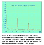
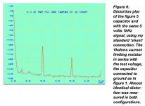
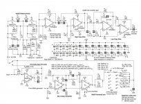
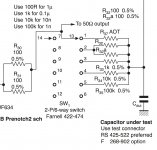
There was some question about the relative distortion of series vs. shunt caps. Bateman measured the difference between series and shunt cap distortion and found them almost identical. Below are relevant clippings from his article showing series/shunt test results, the test-setup, and a closeup of the DUT corner of his testing device.
Attachments
E=1/2CV^2 to find the energy your cap creates, (where C is the capacitance)
then use an NTC thermistor to stop Inrush Current
Is it about electromagnetic guns?
Demonstration of the Navy Electromagnetic Rail Gun prototype - YouTube
Yes, for low order distortions they are bound to be almost the same. At higher orders some difference will be seen, as the ratio between capacitive reactance and feed resistor changes. To put it another way: feeding a current into a cap and measuring the voltage vs. applying a voltage and measuring the current, will give different results for higher order distortions. This is the same algebra as re-entrant distortion from feedback loops.serengetiplains said:Bateman measured the difference between series and shunt cap distortion and found them almost identical.
Yes, for low order distortions they are bound to be almost the same. At higher orders some difference will be seen, as the ratio between capacitive reactance and feed resistor changes. To put it another way: feeding a current into a cap and measuring the voltage vs. applying a voltage and measuring the current, will give different results for higher order distortions. This is the same algebra as re-entrant distortion from feedback loops.
If the distortion mechanism is the same (as it must be) then any difference is related to the external impedances not the cap. I'm not sure what is to be learned from this. The relationship between the phase of the distortion and the fundamental may give a clue as to what part of the cap is generating the distortion. On the RE CLT-1 they give very specific directions on how to scale the measured distortion vs the devices reactance at the harmonic being measured but this makes sense once you understand what is happening.
Using a lower impedance source won't change the nonlinearity, but it will scale the harmonics.
Yes, the cap will behave in exactly the same way to whatever signal it is given. However, the distortion in a current produced by an exact sinewave voltage will be different for higher orders than the distortion in a voltage produced by an exact sinewave current. This is because, for example, the inverse of square (a simple polynomial) is square root (an infinite series).
DF96, maybe you can explain to me why this point is so hard to get across. I'll make it very simple, you shunt a 10,000uF power supply cap with a .1uF bypass. At 2A p-p current in the supply at 1kHz the voltage across the combination is 32 mV p-p and the current in the .1uF is 20uA p-p. What voltage and current makes the "same" distortion as Bateman's test circuit?
BTW WIMA's web site lists (according to MIL-C-19978) polyester/mylar film as only 2-4x worse for DA than PS film, but the distortion in some cases is almost two orders of magnitude worse.
BTW WIMA's web site lists (according to MIL-C-19978) polyester/mylar film as only 2-4x worse for DA than PS film, but the distortion in some cases is almost two orders of magnitude worse.
Last edited:
People aren't used to making order-of-magnitude estimates to determine what issues are worth investigating in more detail and which can be safely ignored. Of course, someone will always come up with a claim that we can hear things well below the noise level so nothing can be ignored. Daft, because we have to ignore lots of stuff: who calculates the probability that all the electrons in their wires will simultaneously jump sideways by 1mm? QM says it is possible, but QM also says it is astonishingly unlikely.
Bateman used a couple of volts, say two order of magnitude higher than 32mV. So you would need 200A of current to get the same level of distortion as he saw. Of course, this assumes that capacitor non-linearity follows a nice smooth law with no discontinuities. I am not aware of any evidence to the contrary. If caps had zero-crossing problems, as some claim, then I would expect that to be well known to the metrology guys and people like Bob Pease would have written about it.
I am puzzled by the fuss about DA. There is no evidence that DA causes distortion, just a little subsonic phase shift. The amount of this can presumably be calculated from careful DC measurements of the relevant caps. There is anecdotal evidence that 'distortion' may be associated with high DA caps, but when we press them it turns out that they are frightened by exponential decays of first order filters - exactly what the maths predicts! This raises questions about the reliabilty of anything else they say.
BTW WIMA's web site lists (according to MIL-C-19978) polyester/mylar film as only 2-4x worse for DA than PS film, but the distortion in some cases is almost two orders of magnitude worse.
I thought we all agreed already that DA is not the source of distortions in caps?
I thought we all agreed already that DA is not the source of distortions in caps?
There was an insinuation that the "other" effects scale with DA so it was a sufficient indicator, this is clearly not so.
We have, but they have not? Scott is pointing out that measured DA and measured distortion are not well correlated.
Relax. It is simple. Do you know why train wheels produce knocking rhythmic sound? Explanation is simple, using the math. Scientific explanation. Wheels are round. Their area is calculated as Pi * Radius squared. You see? Squared! This squares knock. The same way, like square pulses being "distorted" by DA, means DA distorts the sound.
There was an insinuation that the "other" effects scale with DA so it was a sufficient indicator, this is clearly not so.
I meant that even if they scale together it can't be used as a proof of the cause and effect relations. It can be caused by some other underlying effects (theoretically). Or may be unrelated.
I meant that even if they scale together it can't be used as a proof of the cause and effect relations. It can be caused by some other underlying effects (theoretically). Or may be unrelated.
Fair enough, I was leaving the door open so that if there was a corellation it would certainly deserve to be explored. Still stumped on the rectfying terminations cancelling perfectly for sine waves. My theory on that is the tiny amplitude and phase errors are very hard to see on a sinewave, a bridge is less useful because you need an absolute phase and amplitude reference. Another way of saying that is the error signal is the same as the stimulus. The pulse stimulus OTOH gives a characteristic error signal that you can monitor as you null the bridge.
I know the horse is dying, but I must point out bringing up the mysterious rectification in the first plase was an insinuation that there was real harmonic distortion with pulse waveforms and not sinewaves. Which remains an extraordinary claim.
Last edited:
As I proposed before, 2 tones and FFT plot will show everything non-linear that exists. No sidebands = no distortions. Different heights of upper and lover sidebands = PIM. I once found PIM in a tube amp powered from electrolytic caps. Shunted them by a film, PIM gone: sidebands become equal, that means the same order of non-linearities, but soundstage and naturality of wideband sounds improved. Harmonic distortions were very low: -80 dB of 2'nd only, but still audible as PIM. Like scared chicken is afraid of a bush, I now routinely shunt electrolytics by film caps.
- Status
- Not open for further replies.
- Home
- Member Areas
- The Lounge
- John Curl's Blowtorch preamplifier part II