It is not 'rocket science' to understand.
Yep.
Gm Rl is the key.
Nope
The question is does the noise of a resistor go up or down with its value? The answer is both. The voltage noise goes up as the square root of R and the current noise goes down as the square root of R. This simple fact escapes too many people.
This result is fundamental to thermodynamics.
So true, so true.
And often forgotten.
Odin and Tor
I prefer Salas' version, about DIYers. All best new shiny bright products available in stores were initially made in garages, and this is the ever repeated proof of his version.
So true, so true.
And often forgotten.
...by people who "don't amplify power".
I prefer Salas' version, about DIYers. All best new shiny bright products available in stores were initially made in garages, and this is the ever repeated proof of his version.
...by people who "don't amplify power".
If you prefer to read Salas' post that way, that’s ok by me, I don’t care.
We usually amplify power.
I would like to measure the 317 output spectrum by Agilent 2GHz analyzer soon, probably tomorrow.
That wouldn't tell much, you need a network analyzer to measure S21 and S12.
It's a moot exercise anyway, everybody already knows those ICs are not good at high frequencies. As much as "not good" at 2MHz matters for an amp with a 1MHz unity loop frequency.
Good for you, PMA. Let's see some measurements!
It is little understood by many, that the power line in their homes can be polluted with lots of RFI at least to 50MHz, depending on time and location. Much of this can come from their kitchen electric stoves! A long report with measurements was published in one of the IEEE Transactions by IBM, between 10-15 years ago, on this very topic. I can't find it here, with all the other Transactions that I have stored here, maybe someone could do a topic search.
It is little understood by many, that the power line in their homes can be polluted with lots of RFI at least to 50MHz, depending on time and location. Much of this can come from their kitchen electric stoves! A long report with measurements was published in one of the IEEE Transactions by IBM, between 10-15 years ago, on this very topic. I can't find it here, with all the other Transactions that I have stored here, maybe someone could do a topic search.
We are equipped to measure S parameters. Could you describe your request in more details?
If you can measure S parameters with a spectrum analyzer that's absolutely stunning.
I have no requests for you, other than the usual. Post something that fully makes sense, not some half baked, cryptic thing that poses more questions than it answers.
Good for you, PMA. Let's see some measurements!
It is little understood by many, that the power line in their homes can be polluted with lots of RFI at least to 50MHz, depending on time and location. Much of this can come from their kitchen electric stoves! A long report with measurements was published in one of the IEEE Transactions by IBM, between 10-15 years ago, on this very topic. I can't find it here, with all the other Transactions that I have stored here, maybe someone could do a topic search.
John, if you can recall any key words from the title I'll give it a try.
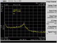
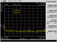
Spectrum measured at power supply board output teminals. 10kHz - 4MHz. PSU loaded by 1.46A output current, and with input mains voltage switched off.
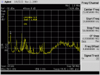
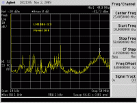
Same for BW 10kHz - 50MHz. We can see a lot of RF pickup even for the PSU switched off.
0dBm means 1mW into 50 ohm, i.e. 224mV approx.
As expected, so I must ask: so what's your point? What are the conclusions of your measurements?
That's before even asking about what and how this was measured, etc...
My point is to show that 'clean' power supply is an issue. It needs careful design, both circuit and box/shielding.
The PSU is pretty conventional, EI 30VA transformer + SB260 bridge + 2200uF + 100nF + LT1084-3.3 + 220uF + 100nF.
The signal is analyzed at PSU PCB DC output terminals. There is no shielding enclosure for the PCB. 3.3V PSU output is loaded by 2.26 ohm.
The output PSU terminal is also connected to RG-58 analyzer cable, this cable terminated by 50ohm analyzer input impedance.
My point is to show that 'clean' power supply is an issue. It needs careful design, both circuit and box/shielding.
.
Thanks for the details. Now, could you clarify a few things:
A) you think your experiment is passing the ACID test?
A) "is an issue" for who/what? What is the impact of these results on an audio amp?
C) you think an open loop buffer will look better?
I would ask at that level how much of the noise is being introduced by the presence of the probe? These measurements are much harder to make with confidence than they seem.
The presence of the RF itself is less of an issue that the modulation on the RF. If the modulation is significant (and coming from a switching supply it may be) any nonlinearity will down-convert it to audio. That down conversion can happen at any stage in the chain.
Seeing this much RF is not uncommon any more. Any populated location in the US is alive with RF. Getting a really RF quiet location is difficult for making open field EMI measurements.
- Status
- Not open for further replies.
- Home
- Member Areas
- The Lounge
- John Curl's Blowtorch preamplifier part II


