What I'm getting from this write-up is that what's being touted is the unremarkable result that a constant impedance load (wrt frequency) will have a constant voltage across it irrespective of the source impedance. IOW, it follows Ohm and Kirchoff.
There's a marketing disadvantage, though- reduced sensitivity to amplifier output impedance and drive capability. Why is that a disadvantage since it's a technical advantage? Take the Wilson speakers, for example. The impedance curve swings mightily and dips down to brutally low levels. So the reviewer will note that the Wilson is far more revealing of amplifier differences than Joe's speaker!
Yep, Focal does this as well, adding components specifically to make this happen in the woofer section. An alternative explanation of course is that they just put in parts that made no difference at all.
For more, see near the bottom here: Focal Profile 918 Analysis
Last edited:
What I'm getting from this write-up is that what's being touted is the unremarkable result that a constant impedance load (wrt frequency) will have a constant voltage across it irrespective of the source impedance. IOW, it follows Ohm and Kirchoff.
Then again if you look at the work NP did on this http://www.firstwatt.com/pdf/art_cs_amps.pdf he does show that for a particular type of driver (lowther etc) which you use well below resonance then a current drive does fatten up the bass nicely. Of course he then cheats with impedance correction network for just the current drive cases, but shows that there are cases where it does make life slightly easier with current drive.
Well that or you need a good story to get lowther lovers to try anything that isn't tubed

T
The "noise" thing is mysterious. In the linked video, Wilson prattles about "jitter," but that of course is total FUD marketing to the ignorant.
It's strange, but I agree with you.
So the views of Wilson should not be interpreted as mine.
OK, so what did you mean by "noise"?
As I said, it is a good question. The problem is that we have to call it something and one definition of noise is "a non-harmonious or discordant group of sounds."
It can be random, it can be source related and then likely harmonically related. The energy has to come from somewhere and it is clearly the amp. A research project is being undertaken and one of the guys is Morris Swift (who says there are no papers that have properly defined this and wants to do it before he retires) and he objects to the use of the word 'noise' as well. Yet it is a generic word that has such a broad meaning, even talking too much is defined as noise. So I shall say as little about it as possible.
I think I must have recommended www.firstwatt.com/pdf/art_cs_amps.pdf to a thousand people out there.
I'm with you on this flat impedance thing, Joe.
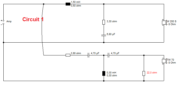
I was shocked how bad this circuit sounded with a regular transistor amp:

And amazed how much better this one sounded:
http://www.diyaudio.com/forums/multi-way/284038-crossover-sounds-better.html
The only real difference is the 22R shunt tweeter circuit has a better, lower ultrasonic impedance, resulting in a much better, cleaner top end. Clearly transistor amps are sensitive to this.
I then speculated that this is why a simple 68R resistor applied before the filter changes the sound for the better.
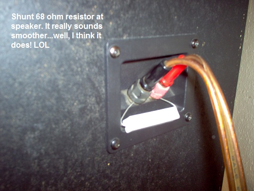
But truthfully, because I know quite a lot about amplifiers and cables, and their limitations at high frequency, this doesn't surprise me. Every time a class AB amp crosses 0V, there is a blip of distortion released, so even ultrasonics become audible as noise.
Your own approach of adding shunt components before the filter is evidently a useful one. TBH, I never quite understand why you use an overly deep undamped tweeter Fs notch, an LC rather than an LCR. You can overdo it, no? The original Usher design appears to have a rising impedance into the ultrasonics, and this is a bad thing, IMO.
I was shocked how bad this circuit sounded with a regular transistor amp:
And amazed how much better this one sounded:
http://www.diyaudio.com/forums/multi-way/284038-crossover-sounds-better.html
The only real difference is the 22R shunt tweeter circuit has a better, lower ultrasonic impedance, resulting in a much better, cleaner top end. Clearly transistor amps are sensitive to this.
I then speculated that this is why a simple 68R resistor applied before the filter changes the sound for the better.
But truthfully, because I know quite a lot about amplifiers and cables, and their limitations at high frequency, this doesn't surprise me. Every time a class AB amp crosses 0V, there is a blip of distortion released, so even ultrasonics become audible as noise.
Your own approach of adding shunt components before the filter is evidently a useful one. TBH, I never quite understand why you use an overly deep undamped tweeter Fs notch, an LC rather than an LCR. You can overdo it, no? The original Usher design appears to have a rising impedance into the ultrasonics, and this is a bad thing, IMO.
Attachments

Last edited:
There's no phase change at all within the audio band. Now, TBH, I don't really worry about deep reverse nulls in crossovers as a measure of quality. My favoured BW3 circuits have no real null at all, being 90 degree phase and power flat. Joe is dealing with an amplifier effect, and I should explain that the 10R/0.1uF Zobel is fitted to a typical bipolar amplifier's output to keep it just stable into open-circuit:
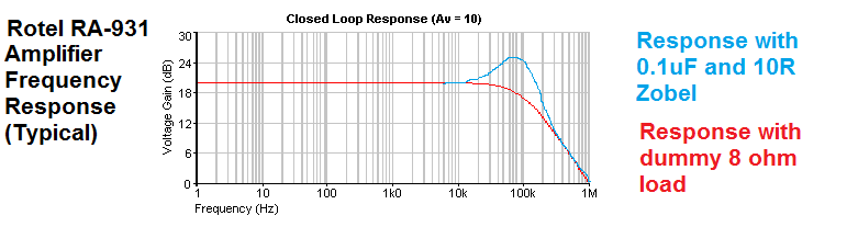
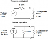
My own view is that feedback works well enough at low audio frequencies. It gets into trouble above 10kHz where the bipolar transistors run out of gain. Maybe valves and MOSfet devices are faster and better? But I don't think that voltage or current drive are the main issue. They can be kind of Norton-Thevenin equivalent.
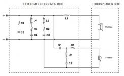
But I'll make a prediction that you can test. If you have a circuit like this that has no shunt path to Earth at high frequency, because coils and drivers go open-circuit, it will sound better with a Zobel of, say 7.5R and 1uF across the speaker terminals, or maybe 22R.
This is part of what Joe is doing. He's also equalising the typical omega 2kHz peak and the bass peak. Less of a worry IMO, but hey, it probably does something.
Interestingly capacitors and cables have significant ultrasonic differences too.
My own view is that feedback works well enough at low audio frequencies. It gets into trouble above 10kHz where the bipolar transistors run out of gain. Maybe valves and MOSfet devices are faster and better? But I don't think that voltage or current drive are the main issue. They can be kind of Norton-Thevenin equivalent.
But I'll make a prediction that you can test. If you have a circuit like this that has no shunt path to Earth at high frequency, because coils and drivers go open-circuit, it will sound better with a Zobel of, say 7.5R and 1uF across the speaker terminals, or maybe 22R.
This is part of what Joe is doing. He's also equalising the typical omega 2kHz peak and the bass peak. Less of a worry IMO, but hey, it probably does something.
Interestingly capacitors and cables have significant ultrasonic differences too.
Attachments
Last edited:
10uF MKP and 24 Ohm resistors
Quite a long way from 7.5R and 1uF, but have fun!
As I said, it is a good question. The problem is that we have to call it something and one definition of noise is "a non-harmonious or discordant group of sounds."
To paraphrase a famous guy, it depends on what the meaning if "it" is. You said:
So what is the primary goal - the one that precedes others in importance? Basically it comes down to 'noise' that many conventional crossovers generate to varying different degrees.
So elimination of "noise" is the primary goal. But you still haven't said what "noise" is- you don't seem to mean the usual engineering definition. What specifically do you mean, then? If it's your primary goal, it has to be defined to see if you've met it, right? What is "it"?
Quite a long way from 7.5R and 1uF, but have fun!
Oh, I know.
Sorry! I needed that for a peak at around 2kHz. Still, in principle, it should ensure the ultrasonic impedance never rises above 24 Ohms.So elimination of "noise" is the primary goal.
As I explained, when you design a speaker you have to have some kind of philosophy and sometimes words are not enough.
But I know that nothing I say will satisfy you, so excuse me for not trying too hard.
As I explained, when you design a speaker you have to have some kind of philosophy and sometimes words are not enough.
But I know that nothing I say will satisfy you, so excuse me for not trying too hard.
If words aren't enough, can you claim to have any philosophy at all? I'm not saying you must be able to define what you feel, but that words are the very nature of theory and philosophy.
It is words that distinguish a theory from intuition.
Hopefully one follows the other in quick succession.
Best,
Erik
I'm with you on this flat impedance thing, Joe.
I was shocked how bad this circuit sounded with a regular transistor amp:
And amazed how much better this one sounded:
Hi Steve
You have stumbled across Wilson's favourite sauce? Not saying though.
Yes, it is quite obvious to what it does to the sound - and if somebody likes it and there is no harm done to the amplifier (try 2 Ohm and drive it with Bruno Putzey's NC400 and I think a lot would be surprised - a bit crazy, but that amp is Class D and sound nice and can handle a crazy low value resistor = 600 Watt).
But not what happens when you flatten the impedance to the max:

Now you can drive the crossover from any impedance !!!
That example is 270 Ohm compared to 0.01 Ohm. It is modeling, but it works in real life and have done it over and over again. Imagine a tweeter with a series high-pass capacitor being driven by 270 Ohm - the tweeter now is asked to become a woofer? It will see everything and the cap will provide zero protection.
But most importantly is what it does to the voltage amp drive, not current drive. Let's face it, we all use voltage drive.
But that 2 Ohm NC400 idea above should be tried with an 8 Ohm speaker system. That amp can do it and it will flatten the impedance and more importantly the electrical phase angle. But you will need a 100W resistor.
I think the key here is not the flat impedance when it comes to the voltage drive. I think the current phase angle is the key and that is what I intuitively seek to achieve even above flat impedance.
Those conjugate filters are actually seen directly by the amplifier. With zero Ohm drive they have zero effect on the crossover, only when we get away from zero Ohm will they come into effect for correct operation of the crossover as seen by the example above. But with voltage drive they are equalising the current from the amp and doing so there is a reciprocal nature between the actual crossover and the conjugate filter - the later is basically a current mirror of a sort.
So if we drive the modified Usher S520 from both sources, it looks like this:
Since Green is current drive and 270 Ohm series impedance, then a current amplifier is always going to have a flat and zero degree phase angle. Now with same arrangement, looking at Red as voltage drive, we are surpringly close and still achieving a respectively low phase angle. I believe that is the key.
Moreover, if I may come back to the crossover again, we know that high and low passes have a Q and that affects the slope. But this is dependent always on always seeing a voltage source looking back. But since our arrangement does not provide a zero impedance source at any time when driving that crossover, then if the response is left unchanged, the Q has to be the same. Yet I reiterate it is not seeing a zero Ohm impedance. That is somehow yet to be explained, but just looking at it, can't we see that is something desirable?
It works with mechanical hgh pass filters as well - especially sealed boxes. For example, a 6-8" driver in a sealed box, figure out the volume and you can design a 2nd order Butterworth alignment. Easy peasy. Let's say FB = 50 Hertz, quite respectable. the response will be -3dB @ 50Hz and -12dB @ 25Hz.
Now construct an LCR centered on 50Hz, adjust it's Q via LC values and adjust R for flatness. Very easy to do via SoundEasy. The impedance will be completely flat.
This is an actual measurement, not modeling:
With this arrangement, both the Q of the box alignment and the Q of the crossover will be locked in forever.
The speaker, its voltages across the voice coils, across every component in the crossover or conjugate (mirror), will be the same irrespective of the source impedance. If the voltages are always the same, the Q are the same, then so is the current.
So I do wonder, is something like pseudo-current drive being achieved since we get the same current conditions under both voltage and current drive? I suspect Esa Merilainen may not agree, but I have speakers here that same pretty much the same (good) when driven by current and voltage - and I like both.
I believe there is something here that needs to be noted and learned from here and I am not alone. A research program is being developed here in Sydney (the home of Sydney University where Thiele-Small Parameters came into being) and what I have done to the Elsinores before the Ushers have been noted.
It is clear that this has brought out a few other like-minded people like yourselves on this subject. That's great.
Final thought, it's clear that Thevenin's Theorum is in part what is at play here. Following TT we can circumvent filter Q's because if a response is for example a 2nd order Butterworth and enforcing rules of TT, it can lock in the Q because of the simple fact, the response curve of a 2nd order filter is not violated. It's always a Butterworth. Same goes for crossovers, the behaviour is the same.
As Morris Swift, one of the "serious guys" down here has asked "what is happening to the Qe of the driver?"
A very good question. The electrical Q is eroded proportionally by the same change percentage wise as the DCR of the VC. Yet it can be circumvented and still be compatible with T-S because SoundEasy's maths is based solidly on that work.
BTW, if anybody who would like to drop in and have a listen, the welcome mat is already at the front door.
Cheers.
It is words that distinguish a theory from intuition.
I fully understand, that is the dilemma here, we have a small group of us here and half don't like using the word 'noise' either. When we find the right word, I can still amend the first post as I have the right to Edit out 'noise' at any time.
Maybe 'noise-floor modulated by current phase errors'? That will depend on more actual data which we will be actively seeking. But certainly, if you read my last post, you will see plenty of reason and intuition.
It is current that makes motion, not voltage. Yet a voltage source can produce any error and yet a current source cannot produce current phase angle error. So more than just intuitively, current error must mean error in tracking.
But I find that, as Solomon said, "one face sharpens another" - so forcing me to explain the above dilemma is a good thing. It helps me to think.
Cheers.
The only real difference is the 22R shunt tweeter circuit has a better, lower ultrasonic impedance, resulting in a much better, cleaner top end. Clearly transistor amps are sensitive to this.
But Steve, what you did was lowering the tweeter sensitivity wrt the rest of the system. Of course you heard a difference, duh!
There's no need to invoke a very unlikely 'transistor amps are sensitive to this' - it is a change in the speaker tonal response and you would hear it with ANY amplifier that has a reasonable flat response.
(Clearly if the amp falls off at 10kHz there's not much coming out of the tweeter and not much you can do at the tweeter).
Jan
Could you post the raw driver responses, and CSD's of the post-modified system if you have them?
Thanks,
Erik
Yes, certainly, but RAW drivers only.
Below are all taken at two Metres and 15 degrees off axis.
MidBass:
As expected for a small driver on a small baffle, diffraction loss is quite high in frequency and then emphasised by a peak around 1Khz and 1.5KHz trough.
MidBass CSD:
Tweeter:
Tweeter CSD:
Gadzooks! I say again, those look like a real challenge integrating at all, never mind the impedance plots.
Yes, certainly, but RAW drivers only.
- Status
- Not open for further replies.
- Home
- Loudspeakers
- Multi-Way
- Joe Rasmussen Usher S520 "Current Compatible" Crossover