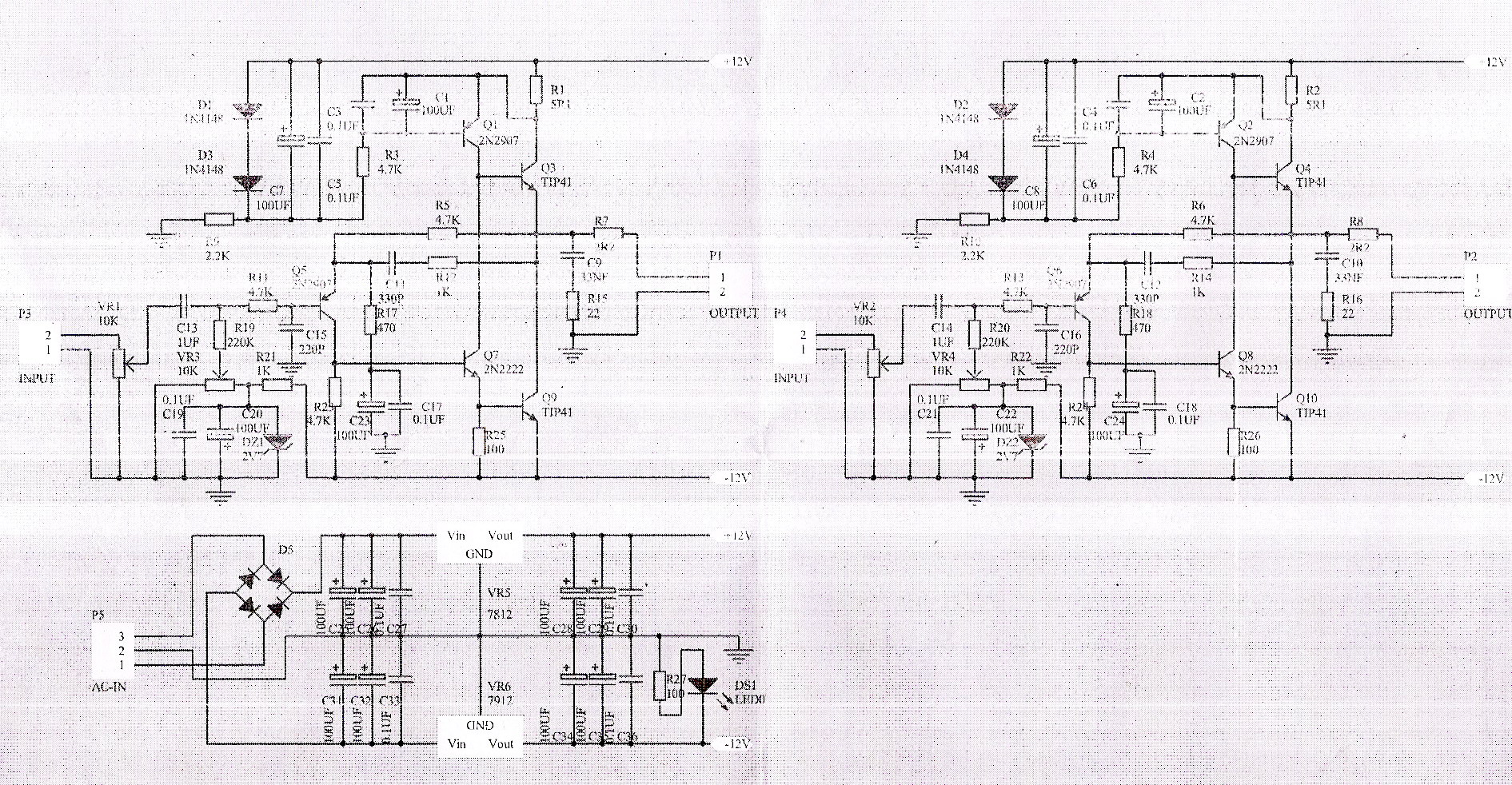
Hey Ricren, the schematic of the dc servo is here (schematic, left down corner).
Source (rockgrotto proboards com): "JHL" headphone amp | Rock Grotto
hello
I think The feedback capacitor C1 must be connected to the ground.
Definitely, otherwise your PSRR will be nonexistent. It might just be a drafting mistake here, at least I would hope so...
Yes, in the orignal circuit diagram, C1 is connected to ground and not to -VCC. Probably an error when drawing the circuit diagram for the DC servo in conjunction with the overall circuit diagram.
Most users have only input and output of the servo integrated in their circuit (this is still connected to ground on the mainboard C1, because no change). Therefore, the system works and no one has noticed the error. ;-)
Sorry about that folks managed to get some sleep.
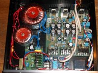
I bought one of these on fleabay (see pic) and wasn't too impressed with the initial sound It turned out they had used horrid ceramic caps on the input,
they were first to go, this brought immediate gains in fidelity.
I then decide to pull all the ceramic bypass caps and replaced with wimas,
more improvement.
Onto the electros, feedback cap 220uF replaced with quality low ESR Sanyo cap
The four smoothing caps replaced with Nichicon low ESR
I felt there was too much gain in the amp to drive HD565 ovation cans, so the 470 ohm was raised to 2K2 .
This thing now sounds fantastic very quiet clean crisp highs and great bass.
I felt the size of the thing was overkill to drive a pair of headphones so decided
to build one on stripboard the new one is less than half size including the 317 337 power supply.
R11 is now 12 ohm R5 is 4K7 C5 R8 C8 and R12 have been omitted. C4 is now 470uF
LM336 2.5v voltage ref used for DC offset.
I cant believe how good this thing sounds for only having 5 transistors
Its dead silent no hum no hiss just great clean music.
And no it doesn't oscillate.
Hi Hotiron,
I'm considering building the eBay JLH/JHL Class A headphone amp to be used with headphones or little full range speakers nearfield. Do you think this little amp has the oomph or should different output transistors be used? I've heard that BD139's and BD140's could be used.
thanks!
")
Thank you Eric! Now I need to figure out which of the eBay sellers use the correct circuit. lolHi Marc,
The MJE15030 are much better sounding vs the usual BD139.
BR,
Eric
... how to connect DC servo ?
Hi kudrik,
I have marked the connection points for the DC-servo in the schematic and on the PCB (please look at the attached photos). I hope this helps you.
Best wishes
Steffen
An externally hosted image should be here but it was not working when we last tested it.
An externally hosted image should be here but it was not working when we last tested it.
Hi,
I'm tempted to order one cheap ebay model to play with... Inspecting the pictures of its PCB posted here I was wondering what was the purpose of the track between the two "-" of the output connectors with a pad near the pot ? If I understand correctly it look like a ground loop ?
Is there "better" PCB design available elsewhere ?
which post?.............. Inspecting the pictures of its PCB posted here....................
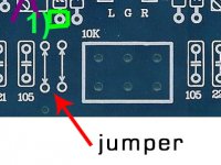
post #648, third picture, track at the bottom of imagewhich post?
Hi,
Inspecting the pictures of its PCB posted here I was wondering what was the purpose of the track between the two "-" of the output connectors with a pad near the pot ? If I understand correctly it look like a ground loop ?
The first time I used those negative outputs on the side of the board, I had quite a bit of hum with the volume pot near its lowest setting.
If that jumper is what you mean, then I think the designer is trying to make a star ground.Hi,
I'm tempted to order one cheap ebay model to play with... Inspecting the pictures of its PCB posted here I was wondering what was the purpose of the track between the two "-" of the output connectors with a pad near the pot ? If I understand correctly it look like a ground loop ?
Is there "better" PCB design available elsewhere ?
I guess he try to use 0 Ohm resistor when space available, but when the space is not fit for a 0 Ohm resistor, he use wire jumper instead.
Attachments
Hi,
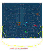
sorry for being not specific enough. I was talking about a signal ground loop between this track (in yellow in my pic) and the output signal ground wires from the connectors to the output headphone jack. Does it make sense with the attached pic ?
sorry for being not specific enough. I was talking about a signal ground loop between this track (in yellow in my pic) and the output signal ground wires from the connectors to the output headphone jack. Does it make sense with the attached pic ?
Attachments
On the post #648 schematic, these points are noted "OUTPUT P1-2" and "OUTPUT P2-2", both tied to ground.where do those two tapping points/pads go on the schematic?
I don't think so Andrew, as showed by kroto in post 654, there is a jumper between this trace and the ground.p1-2 is connected to P2-2 by a ;ong trace. This trace also connects to a number of other components. But not to the Power Ground.
Looks like the sch does not match the PCB.
Could someone with the PCB confirm this ?
- Home
- Amplifiers
- Headphone Systems
- JLH Headphone Amp